8.3 Creating Service Configuration Definitions
Create service configurations for any element under the hierarchy. Each generated service configuration is based on rules defined when creating the definition.
Each service configuration definition is comprised of five types of subdefinitions that determine how the hierarchy is shaped and built:
-
Structures: When defining structures, you are defining what the service configuration will look like. An existing element hierarchy is modelled to build out the new service configuration’s structure. For example, if using a BDI adapter or OpenView maps as the base structure, the hierarchy of the newly created service configuration looks just like the selected BDI or OpenView maps hierarchy. Based on matching rules, the object hierarchy is copied along with algorithms, icons, or menu options.
-
Sources: When defining sources, you are defining how state and property information is applied to the service configuration’s objects. Join rules are used to apply state and property information from an existing element hierarchy to the new service configuration objects. This can be a T/EC, BEM, or OpenView adapter or any other hierarchy that can provide state and property information to the configuration objects.
-
Dependencies: When defining dependencies, you are defining various relationships that can be viewed in the Relationship browser from the service configuration’s objects. Select points in the service configuration definition that rely on elements from other branches, or indicate implied relationships. These relationships may contribute to state of the service configuration. Dependencies can be defined using existing dependencies (consumers) or those generated from alarms (generators).
-
Modeling Policies: When defining modeling policies, you’ll set up options used when generating the service configuration. Generation options set up how state is propagated, property data is integrated, and how definitions contribute to the configuration. Correlation options are additional rules that determine which element are included in the new hierarchy. Scripting options allow a script to be run on the configuration elements during generation. Algorithm options allow inherited algorithms to be overridden by new algorithm policy definitions.
-
Schedule: (Optional) Create a schedule to update and refresh the service configuration.
HINT:When building a complex configuration, subdivide the task into smaller steps. Build smaller configurations based on these smaller steps, which act as test modules, before building the complete configuration.
The high-level steps for creating a service configuration are:
-
Create a Service Configuration definition by naming the definition and selecting a general reconciliation policy.
For instructions, see Section 8.3.1, STEP 1: Create the Service Configuration Definition.
-
Select structures for the configuration by selecting an existing hierarchy.
For instructions, see Section 8.3.2, STEP 2: Define Structures.
-
Select sources that should supply state and property information to elements in the new structure.
For instructions, see Section 8.3.3, STEP 3: Define Sources.
-
Define dependencies where the new configuration relies on other branches or relationships.
For instructions, see Section 8.3.4, STEP 4: Define Relationship Dependencies.
-
Define modeling policies to determine how the configuration is generated and correlated. Also set up scripts to run or algorithms to apply to the configuration.
For instructions on setting generation options, see Section 8.3.5, STEP 5: Select Generation Options.
For instructions on selecting the type of correlation used with objects, see Section 8.3.6, STEP 6: Select Element Correlation Options.
For instructions on defining a script to execute at generation-time, see Section 8.3.7, STEP 7: Apply Scripts.
For instructions on applying custom algorithm rules, see Section 8.3.8, STEP 8: Configure Custom Algorithms.
-
Generate the configuration to determine if the generated tree meets expectations.
For instructions, see Section 8.3.9, STEP 9: Test and Generate the Configuration.
Verify that the configuration builds as expected in the Operations Center console. Make changes, then regenerate to make available to users.
-
Apply security permissions to specific element hierarchies to prevent unauthorized users from viewing them. Also prevent display of these elements in the Show Impacted dialog.
-
Create a schedule for the automatic refreshing or generation of the configuration.
For instructions, see Section 8.3.10, STEP 10: Schedule Updates (Regenerations) of the Configuration.
8.3.1 STEP 1: Create the Service Configuration Definition
The Service Configuration Editor is used to create service configuration definitions. Service configurations can be defined from any existing service model elements or as part of the process when adding a new element to the hierarchy.
To create a service configuration:
-
In the Explorer pane, expand > .
-
Do one of the following:
-
To create a service configuration from an existing service model, right-click a service model element, then select > .
-
To create a service configuration on creation of a new service model, right-click the parent element, then select . When defining the element definition, select the check box. After the service model is created and property pages are closed, the Configuration Editor automatically launches.
-
-
In the confirmation dialog box, click one of the following buttons:
Yes: Creates a service configuration. If developing a configuration for the first time, consider enabling the debug features.
No: Opens the editor settings for debug, auditing, and element locking features.
For more information, see Section 8.4, Enabling Auditing, Debug, and Element Locking During Generation.
The Service Configuration Editor opens:

-
Specify a service configuration name in the field.
-
From the drop-down list, select a method for reconciling elements when generating the configuration:
None: Overwrites elements without deleting old elements first.
Merge: Combines the new configuration with any existing structure.
Delete-Before-Execute: Removes any existing structure before generating the new structure.
WARNING:Carefully consider the Reconciliation Policy in use when generating configurations, while users are actively using views. The Delete-Before-Execute policy is the most disruptive to active users. However, in development mode, this is the most desirable option because the new hierarchy is created from scratch instead of from merging existing elements.
-
Click Save.
8.3.2 STEP 2: Define Structures
Model the new hierarchy on an existing element hierarchy. Structures copy existing element branches to form a new hierarchy. Use hierarchy depth selections and matching rules to select elements of interest.
To create a structure definition:
-
In the Explorer pane, right-click a service model element for which you have created a service configuration, then select > to open the Service Configuration Editor.
-
In the Service Configuration Editor Definition Navigator pane, click
 ().
().

A new Structure definition displays in the hierarchy. The definition remains unnamed until the is selected.

-
Click
 () to select an element for the .
Select an element whose child structure should be used as a model for the new hierarchy.
After selecting the element, the definition element in the Definition Navigator updates to display the selected root element.
-
Use the spinner or specify the first level of children for the structure to include under the selected .
Leave at 0 to include the selected root element.
-
Use the spinner or specify the deepest level of children to include under the selected .
Leave at 0 for to include all levels of children.
-
To create a matching rule, click
 (), then complete the Add Match wizard.
Matching rules are used in multiple areas of Operations Center. For a complete explanation of creating and applying matching rules, see Assigning Elements by Matching Properties.
The Matching Rules specify criteria for selecting elements in the source hierarchy as candidates for the join rules (explained in the next step). The default Name Matcher uses the element name. However, it is also possible to match element DName or properties.
-
Click .
8.3.3 STEP 3: Define Sources
After defining the element structure, define sources for obtaining state and property information for the elements. Use join rules to apply state and property information from a source hierarchy to the new service configuration.
There might be situations where no source definitions are defined. These include configurations that:
-
Derive source information from the structure elements. For more information, see STEP 5: Select Generation Options.
-
Show structure only, by design. In this case, there is no need to expose any state information.
-
Are defined only for their structure, which is leveraged by other (second generation) configurations. In this case, element state is configured for the second generation configuration hierarchies.
The source definition consists of existing elements that provide state and property information to the new service configuration. The source can be a T/EC, BEM, or OpenView adapter or any other element hierarchy that can provide source information.
IMPORTANT:When a configuration copies properties from structure elements while requiring a match in the join rule, Structures and Sources must not be defined in the same definition. The first definition must define Structures, while Sources are defined in a second and separate definition. The join rule is defined inside the Sources definition.
For more information on join rule settings, see Using Join Rules. For more information on copying properties from structure elements, see Section 8.3.5, STEP 5: Select Generation Options.
To create a source definition:
-
If you’ll be using the option in the Source join rule AND want to copy properties from the Structure elements, create a new definition.
For information on join rule settings, see Using Join Rules. For information on copying properties from structure elements, see Section 8.3.5, STEP 5: Select Generation Options.
-
In the Service Configuration Editor, click
(New Definition) to create another configuration definition.
The new definition element is added beneath the existing definition in the tree.
-
Enter the new definition name.
Note that illustrations in the following steps do not reflect the requirement of needing two definitions.
-
-
In the Definition Navigator pane, click
 ().
().

A new Source definition displays in the hierarchy. The Source definition remains unnamed until the is selected.

-
Click
() to select the .
Select any element that can supply state or property information.
-
(Optional) Restrict the source by specifying a start and end hierarchy level in the and fields.
Leave at 0 to include the selected root element.
Leave at 0 for to include all levels of children.
-
To create a matching rule, click
(), then complete the Add Match wizard.
Matching rules are used in multiple areas of Operations Center. For a complete explanation of creating and applying matching rules, see Assigning Elements by Matching Properties.
The Matching Rules specify criteria for selecting elements in the source hierarchy as candidates for the join rules (explained in the next step). The default Name Matcher uses the element name. However, it is also possible to match element DName or properties.
-
To create a joining rule, click
(), then complete the Add Join Rule dialog.
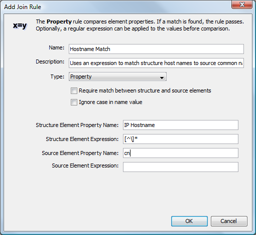
Join rules specify how to match the source elements and the element in the new configuration. The default rule matches element names. You can also match elements by property, script, hostname, or substring name. Rules are evaluated separately. If a match is found, the rule applies and a join occurs.
For more information, see Using Join Rules.
-
Click .
Using Join Rules
The join rules specify how to correlate source elements with elements in the new configuration. The default rule matches element names. You can also correlate elements by property, script, hostname, or substring name. Rules are evaluated separately. If a match is found, the rule applies and a join occurs.
Creating Join Rules
To create a new joining rule:
-
Click
() to open the Add Join Rule dialog box.
-
Select the type of rule from the drop-down list.
Name: Compares element names. Optionally, a regular expression can be applied to the values before comparison.
Property: Matches element properties based on the property names specified for both the source and structure. Optionally, a regular expression can be applied to the values before comparison.
Script: Passes the structure and source arguments to the script to evaluate if a join should occur. The last line of the script must indicate a True/False response.
Host Name: Compares element names, taking into consideration simple hostnames and fully qualified hostnames (FQDN).
Substring Name: Compares element names to determine if one name is contained within or is the same as the other.
The other fields in the dialog box change accordingly.
-
The fields in the Add Join Rule dialog box change depending on the type of join rule. Fill in the fields on the dialog box for the rule type.
For example, these fields are common to all join rule types:
-
Require match between structure and source elements: Select this option to apply all specified Matching Rules when applying the join rules. When selected, structure elements are not copied unless a match occurs. Clear the option to ignore the Matching Rules and only apply the Join Rules. When cleared, all structure elements are copied based on Join Rules only.
IMPORTANT:If you select this option to require a match, and intend to copy properties from structure elements, you must define two separate definitions the Service Configuration to handle structure and source. Use the first definition to define the structure, then create a new definition to define sources. The join rule with this restriction is then set for the source inside the second definition.
For more information on copying properties from structure elements, see Section 8.3.5, STEP 5: Select Generation Options.
-
Ignore case in name value: Select this option to ignore the letter case when comparing source and structure criteria. Clear the option to consider the letter case.
and fields apply to Name and Property type join rules. Use regular expressions to perform a query before applying the join rules. For more information about using expressions, see Understanding Expressions Used in Join Rules.
-
-
Click OK.
Understanding Expressions Used in Join Rules
There is an option to query the structure and source elements using a regular expression or a macro expression before applying a name or property type of join rule.
Macro expressions provide increased flexibility in defining query text. They provide embedding control statements and variable substitution in query statements. Macro expressions use Velocity syntax. Velocity is a third party package provided by the Apache Organization and bundled into Operations Center. Documentation for Velocity is available at http://velocity.apache.org/engine/devel/user-guide.html.
Some of the Velocity syntax rules are:
-
No spaces are used in macro expressions.
-
The notation for a variable consists of a leading “$” character followed by a Velocity Template Language (VTL) identifier. A VTL identifier must start with an alphabetic character in curly brackets.
-
Characters in a macro expression are limited to:
-
Alphabetic characters (a–z or A–Z)
-
Numeric characters (0–9)
-
Hyphen (–)
-
Underscore (_)
-
Use expressions to construct property lookups based on either parent or child element names. For example, use $parent.name to return the name of a parent element, then look up a specific property. Table 8-1 shows parameter variables specific to Operations Center.
Table 8-1 Operations Center Parameters
|
Variable |
Returns |
|---|---|
|
${parent.name} |
The name of the parent element. To traverse the tree to return values for non-immediate parents, add additional parent. declarations for each parent level. For example to return the name of the grandparent, use $parent.parent.name; and for two levels higher, use $parent.parent.parent.name. |
|
${parent.class} |
The class of the parent element. |
|
${sourceElements} |
The names of a service model’s linked source elements. |
|
${sourceElementProperties} |
A comma-delimited list of all property values for service model’s linked source elements. See the ${childrenProperties} entry below for an example of a property lookup. |
|
${children} |
The names child elements. |
|
${childrenProperties} |
A comma-delimited list of all child property values. For example, the children of an element have a Location property, and there are three children having the following Location values: Chicago, Washington, and Miami. Use the expression $childrenProperties.get("Location") to return the value Chicago,Washington,Miami. |
Expressions are useful when there is a need to correlate child element data containing multiple values that are a number of levels beneath the joining point of the source and structures element hierarchies.
A common use case involves the existence of multiple IP addresses on a host element. Assume there is a need to correlate a structure element, which has one or more IP address values (either in its name or a property), with a source element that intersects one of these IP address values (in either its name or property). An additional factor could be that the value of a property required to correlate an element resides in a fixed location under the element structure.
The following is an example source element hierarchy. Multiple IP addresses are elements modeled under the host element (Host A).
Host A
   Application
      Interfaces
         IP:206.55.26.1
         IP:206.55.26.2
         ...
To join this with a structure element named “206.55.26.1” requires joining at the IP: 206.55.26.1 element. However, the actual join point is Host A, which is two levels up. The solution requires using a combination of the $childrenProperties and a regular expression to extract IP addresses from specific properties.
The property join rules allow using a regular expression to extract data from a string. Assume the structure contains the property “name” that contains multiple IP addresses as property values. The first part of the solution is to use the following regular expression:
\d{1,3}\.\d{1,3}.\d{1,3}.\d{1,3}
This expression obtains the first IP address from a string. For example, in the string IP: 206.55.26.1, it returns 206.55.26.1.
To extract multiple values (multiple IP addresses in this example), use a group expression by placing parentheses around the original expression:
(\d{1,3}\.\d{1,3}.\d{1,3}.\d{1,3})
The group operator locates and joins all matching IP values.
This solution can extract repetitive groups, such as multiple IP addresses in a property that are comma-delimited or space-delimited. For example, if a string contains multiple IP addresses, in the form of 192.168.1.1,192.168.1.3 or 192.168.1.1|192.168.1.3 or 192.168.1.1 192.168.1.3 (or any other delimiter), apply the regular expression (\d{1,3}\.\d{1,3}.\d{1,3}.\d{1,3}) to these string values to return two group values that are used to intersect the join.
The second part of the solution looks up a property located in a fixed location in the source element hierarchy. Use ${children} and ${childrenProperties} to extract the IP address values. Using the example element structure listed above, use this expression:
${children.get('Application').children.get('Interfaces').childrenProperties.get('name’)}
This returns a comma-delimited list of the names (such as IP: 206.55.26.1, IP: 206.55.26.2).
In summary, the following expressions are used to correlate child element data and multiple values:
-
Use ${childrenProperties} to extract the IP address values embedded in the names within the element structure. This returns a comma-delimited list of names (such as IP: 206.55.26.1 or IP: 206.55.26.2).
-
Uses the grouping regular expression (\d{1,3}\.\d{1,3}.\d{1,3}.\d{1,3}) to return the two values (or any number of values).
Figure 8-1 shows both expressions entered in the Edit Join Rule dialog box:
Figure 8-1 Edit Join Rule Dialog Box
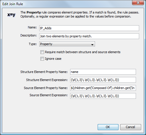
This join rule matches IP addresses between the source and structure using a combination of the ${childrenProperties} and a regular expression to extract IP addresses from specific properties.
8.3.4 STEP 4: Define Relationship Dependencies
Dependencies define points in the new hierarchy that rely on elements from other branches, or indicate an implied relationship. Based on selections, these relationships could contribute to state.
Dependencies defined relationships that can be viewed in the Operations Center Relationship browser. To open the Relationship browser, right-click an organization, then select . For more information about using the Relationship browser, see Section 6.0, Understanding Element Relationships.
Figure 8-2 Service Configuration Editor: Defining Dependency Definitions
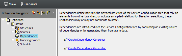
To define the types of dependencies, review the following sections:
-
Defines relationship based on an existing dependency source.
-
Defines relationships based on associations from alarm data.
Using Dependency Consumers
Use dependencies currently available in a hierarchy to further define the configuration. Many discovery tools look for and save information about dependencies in the network. Use a dependency consumer definition to select from and leverage any known dependency relationships.
Creating a Dependency Definition Using Existing Dependencies
-
In the Definition Navigator pane, do one of the following:
-
Click
 ().
().
-
Click the element, then click the link.

A new dependency definition displays in the hierarchy. It remains unnamed until the element is selected.
-
-
Click the
() to browse, then select the base element for the dependency rules.
-
Add, edit, or remove join rules as necessary.
Join rules specify where to merge elements from the tree into the configuration.
Specify join rules matching using Name, Property, Script, Host Name, or Substring Name.
For more information, see Using Join Rules.
-
Click .
Selecting Dependency Relationships to Include in the New Hierarchy
The next step is to select dependencies from the selected element:
-
In the section, click
().
A dialog box displays existing dependencies for the selected element:

-
Select one or more dependencies, then click .
The selected dependencies display in the section:

-
Select the check box, then specify the type of dependencies to capture:
Either side: Resolves using either source (origin element) or target (termination element).
Source to target: Resolves from source (origin element) to target (termination element) only.
Target to source: Resolves from target (termination element) to source (origin element) only.
Partial dependencies are relationships in which the dependency does not exist for both elements. For example, the source might be dependent on the target element, but not vice-versa.
-
To allow dependency elements to contribute to state, select the check box.
-
Click .
Adding a New Dependency Element
The alternative to selecting known dependencies is defining a new dependency.
To add a new dependency element:
-
In the section, click
().
-
In the field, enter an expression that matches dependencies, then click OK.

-
(Conditional) To edit the expression used to select a dependency, select the dependency from the list, then click
 ().
().
-
(Conditional) To delete a dependency, select a dependency from the list, then click
 ().
().
Using Dependency Generators
If no dependencies are available, create dependencies using alarm information from any source. Matching an alarm property with an element property establishes element relationships that previously were unknown.
Each dependency has an origin and a termination. In other words, this establishes the element where the dependency starts (From) and the element where the dependency ends (To).
To say that a is dependent on means that the dependency relationship exists from (origin element) to (termination element).
To create a dependency definition from alarm information:
-
In the Definition Navigator pane, do one of the following:
-
Click
().
-
Select the element, then click the Create Dependency Generator link.

A new dependency definition displays in the definition hierarchy. It remains unnamed until the is selected.
-
-
Click
() to select the element whose alarms are the .
-
Select the check box to allow matched dependency elements to contribute to the state of configuration elements.
-
Add detail to the dependency names by including a property in the dependency naming convention.
-
In the field, specify an alarm or element property using the syntax as described in the dialog box.
-
Use the settings to define where and how the dependency originates:
Alarm Property: In the field, specify the alarm column name that matches the Element Property for matched elements.
Element Property: In the field, specify the element property name that matches the Alarm Property value.
Element Root: Click
() to select the where elements are selected for matching values with values.
Matching Rules: Define matching rules in the list. Matching rules select elements under the to use for dependencies. For more information, see Creating a Matching Rule.
-
Define dependency Termination settings, which determine how the dependency ends.
For information on setting definitions, see the previous step.
-
Click .
8.3.5 STEP 5: Select Generation Options
Use > options to specify advanced features that define how to generate the new configuration structures and how to apply source and property data. These include options for propagating state, integrating property data, and deciding how definitions contribute to the configuration.
For example, source elements can automatically display as children in the new configuration. Under certain circumstances, choose to derive property, and state calculations from structures instead of sources.
To set options for generation of the service configuration hierarchy:
-
In the Definition Navigator pane, expand .
-
Click .

-
Select the option to include source elements in the new configuration hierarchy as linked children of the service model.
This feature is the same as the option in the Elements property page for a service model element. For more information, see Section 3.1.1, Assigning Elements to a Service Model.
-
Select one or more of the following check boxes, to indicate how the structure of the configuration is to be generated and what attributes are copied:
Create state relationship link to structure elements: Select this option to apply state propagator mechanisms from structure elements. When selected, configuration objects are linked to the original structure elements in order to inherit state information from them.
Copy properties from structure elements: Select this option to copy properties from original structure elements. When selected, but not the above Create state relationship link to structure elements option, the properties, but not states, are inherited from the structure’s elements.
IMPORTANT:If copying properties from structure elements AND you have selected for any Source join rule, Sources must be defined in a new and separate definition from Structures. In this case, this option is selected in the generation options for the first definition set up for Structures.
For more information on defining sources, see STEP 3: Define Sources. For more information on join rule settings, see Using Join Rules.
Delete null structure attributes from the generated element: When selected, element properties with a null value are not copied from structure elements.
Include the structure from source elements at match points: Select this option to build a structure from both source and structure elements when the join rule matches. When selected, at the point the join rule is found to be true, the new configuration structure is built by combining the object hierarchies from the base elements as defined in both and .
Include the structure from elements linked to service model elements: Select this option to include any linked elements found under the base elements defined in . This applies only when a Service Model hierarchy is identified in the subdefinitions. Keep this option unselected to include only service models elements that are not linked objects.
Generate links to correlated elements: Select this option to create linked objects of correlated elements instead of copying them to build the new configuration.
Do not match against elements linked to sources: Select this option to exclude any linked children under source elements. When selected, only direct children are matched.
-
Select the check box to implement a MODL file to build the configuration hierarchy.
A MODL file can be used to generate matches to target elements using structure or source values. MODL is the Managed Object Definition Language.
For more information on using MODL, see the Operations Center 5.6 Adapter and Integration Guide.
-
Hierarchy File: Select a hierarchy file that contains an XML description of the hierarchy of elements to build below the configuration element. Specify a relative filename in the /OperationsCenter_install_path/database directory. Sample hierarchy files can be found in the /OperationsCenter_install_path/database/examples/BSCM directory.
-
Stylesheet File: Click
() to select a stylesheet file.
-
Use Structure Element for Initial Tree: Select the check box to apply hierarchy file elements to bottom of structure elements.
-
-
Click .
8.3.6 STEP 6: Select Element Correlation Options
> uses matching rules to determine which elements are included in the element hierarchy generated by a service configuration.
By default, correlation is used and applied to all elements that meet the , , and other rules in the definition of the service configuration. Meaning, all matched elements are included.
As an alternative, correlation type can be set to so that the new configuration is built including only those elements that do not matching rules. All matched elements are excluded.
For more complex correlation needs, matching uses expressions that generate matches based on values extracted from structure and source elements, to determine which elements are included in the output hierarchy.
To define how elements in the new configuration are correlated:
-
In the Definition Navigator pane, click the element under .

-
Select one of the following options under to define how the new configuration is correlated:
-
Static: matching is the default. All elements that meet the , , and other rules in the service configuration definition are included in the outputted hierarchy.
-
Inverse: matching is basically the opposite (or “not” version) of static matching. It means that all elements that meet the Structures (and optionally Sources) rules but do not meet all other rules of the definition are included in the output hierarchy. This option is typically used to create or find elements that are missing.
-
Dynamic: Select matching to define an expression template that generates a match based on values extracted from structure and source elements, to determine which elements are included in the output hierarchy. The types of expression templates are as follows:
-
REGEXP: Selects elements based on a regular expression.
-
LDAP: Selects elements based on an LDAP expression.
-
Script: Selects elements based on a script written using the NOC Script language. The script must evaluate to either True or False for each element.
-
Fixed: Performs the same as static matching except that you can add parameters to further define elements included in the output hierarchy.
When matching is selected, there is an option to restrict matching to only the elements specified under (for more information on sources, see STEP 3: Define Sources). To match only the base elements, select the check box.
For more information on defining expression templates, see Understanding Expression Template Parameters.
-
-
-
Click .
Understanding Expression Template Parameters
The following parameters can be used in an expression template:
-
${name} for element name
-
${class} for element class
-
${propertyName} for any other property of an element for which correlation applies, such as ${IPAddress} for the IPAddress property of an element
-
${parent.name} to look up the value of the parent to further define the expression
-
${parent} to allow for the template to introduce parent values to the resulting match for any property, such as ${parent.class} or ${parent.propertyName}
Parameters must be specified using Velocity syntax. Operations Center uses Velocity, which is a project of the Apache Software Foundation, as a macro processor and template language. Documentation for Velocity is available at http://velocity.apache.org/engine/devel/user-guide.html.
Some of the syntax rules are:
-
No spaces are used in macro expressions.
-
The notation for a variable consists of a leading “$” character followed by a Velocity Template Language (VTL) identifier. A VTL identifier must start with an alphabetic character.
-
Characters in a macro expression are limited to:
-
Alphabetic characters (a–z or A–Z)
-
Numeric characters (0–9)
-
Hyphen (–)
-
Underscore (_)
-
Because the template language is Velocity, the template can use standard java string manipulation functions to customize the output. A common use is to apply a regular expression to transform a part of the string:
${name.replaceFirst('\..*', '' )}
This macro takes the value of the element name, and replaces all values from the first period to the end of string with the empty string (''). This is useful for shortening the name to an unqualified hostname, for example.
In addition, a common use of the ${formula.util()} macro expansion is to encode a DName component with URL encoding syntax:
${formula.util.encodeURL($name)}
This is required for formatting a DName in the proper match output to escape spaces into + characters. This, however, must be combined with a replaceAll() macro to turn the + characters into non regular expression characters:
${formula.util.encodeURL($name).replaceAll('+','\\+')}
In this example, if the input ${name} has the value of One, Two, Three, the output should end up as One,\+Two,\+Three, first by passing through the URL encoding to produce One,+Two,+Three, then the replaceAll to achieve the final result.
Multi-generational SCM definitions now allow the destination element of a SCM definition to appear in the structure position. This enables additional correlation steps after the first pass through a generation.
8.3.7 STEP 7: Apply Scripts
> allows scripts to be run on configuration elements any time the configuration is generated.
Scripts are often used to:
-
Issue alerts that allow proactive management when a view has changed or something is actionable. Script alerts can create alarms, send e‑mail notifications, play a sound, or issue any other automation event.
-
Create a trouble ticket when an element is critical, but does not have an associated ticket.
For example, if a configuration looks at both test and production systems and then overlays a change management system, a script might signal an alert when something is different between test and production systems, but a change order does not exist.
Under > , define scripts to run:
-
Pre Definition: the script runs before any elements are generated by the definition.
-
Post Element Generation: the script runs after an element is generated by the definition.
-
Post Definition: the script runs after all elements are generated by the definition and is the last thing executed by the configuration’s job.
IMPORTANT:Never use configuration scripts to invoke another SCM configuration job.
To process newly created elements with a script:
-
In the Definition Navigator pane, click to expand the element under . to define a script for use with new elements within the service configuration.

-
Do one of the following:
-
Click to define a script to run before any elements are generated by the definition.
-
Click to define a script to run after each element is generated by the definition.
-
Click to define a script to run after all elements are generated by the definition and is the last thing executed by the configuration’s job.
-
-
Select the check box.
-
Enter or paste the script code in the Script text area.
The util class, (scripting engine), supports $formula.util.encodeURL($objectClass), and access to $formula.Root and $formula.Elements, and so on.
If defining a Pre Definition script, return the string “abort” to cancel definition generation.
For information about scripting, see the Operations Center 5.6 Scripting Guide.
-
Click to save the definition settings.
8.3.8 STEP 8: Configure Custom Algorithms
By default, a configuration inherits algorithms from Structure definition elements. However, it is possible to use algorithm policy definitions to override inherited algorithms for matched elements. An algorithm definition uses matching rules to select the elements to which an algorithm is applied.
To create an algorithm for elements in the new service tree:
-
In the Definition Navigator pane, click the element, then click the Create Algorithm link in the right pane.

-
To add, edit, or remove Matching Rules for the algorithm, do any of the following:
-
To define a new rule, click
().
-
To edit a rule, double-click it.
-
To delete a rule, select a rule, then click
().
Matching rules are used in multiple areas of Operations Center. For a complete explanation of creating and applying matching rules, see Assigning Elements by Matching Properties.
-
-
To specify the algorithm to use in calculating matching element conditions, select one of the following options:
-
Select the radio button to apply all default algorithms.
-
Select the radio button to customize the algorithm setting for the matched elements.
If you select an alternate algorithm, click the drop-down list, select an algorithm type, then specify options based on the algorithm type.
For detailed information on algorithms, see Using Algorithms to Calculate Element State in the Operations Center 5.6 Server Configuration Guide.
-
-
Click to save definition settings.s
8.3.9 STEP 9: Test and Generate the Configuration
Generating a configuration builds a new hierarchy beneath the service level element where the configuration is defined. As a general practice, generate the new configuration and check the results before allowing users access to it.
Once in production, schedules can be used to automatically update the configuration for users. Regeneration on a timely basis ensures that new information and elements are accessible from the service hierarchy.
HINT:Generate service configurations directly from the Operations Center console. Right-click the element where the configuration is defined, select , then select .
Definition options allow you to enable configuration element locking during generation. When enabled, the service configuration may not be generated manually or by scheduled process as long as a user or another process has the service configuration element locked. For more informaton about enabling or disabling the element locking feature during generation, see Section 8.4, Enabling Auditing, Debug, and Element Locking During Generation.
To generate the configuration:
-
On the toolbar, click
 Generate.
The service configuration is generated based on definition settings.
As the configuration generates, the following prompt asks if you want to hide the generation process in the background:

-
Do one of the following:
-
Click to allow the generation to continue in the background.
-
Click to stop the configuration generation in progress.
The following message displays when the generation process is complete. It displays the total time used to complete the generation.

-