12.1 Lifecycle Support: Time-Based Snapshots to Manage Changes
Supporting the Change Management lifecycle can be a daunting task. Using SCM, views can be created to show the technology and state of the production environment. If a snapshot can be taken of these views, in order to create a proper baseline, then as the production environment view updates and changes, it can be compared to the baseline snapshot in order to expose any changes.
12.1.1 Scenario Description: Production Environment Baseline
This scenario uses:
-
A Service Catalog hierarchy that shows a simple listing of all key services
-
A discovery tool that provides discovery on networks and dependency information
-
A Tivoli T/EC Adapter that provides state information to newly discovered objects found as a result of discovery by the discovery tool
-
Two different service configuration definitions that build the Production Snapshot and Production Candidate views
In this example, the goal is to create an accurate view of a production environment, to use as a baseline snapshot of all the networks. As changes occur in the network environment, identify the services affected by these changes by comparing the snapshot baseline with the current Network view.
-
Start by taking a snapshot or baseline of the environment.
To do this, define a service configuration that creates a Production Candidate hierarchy, which shows key business services and the technology that supports them. This view remains an active and constantly updated view of the network.
-
Create another configuration named Production Snapshot.
-
Take a “picture” of this view, then save it as Production Snapshot, which becomes the baseline view:
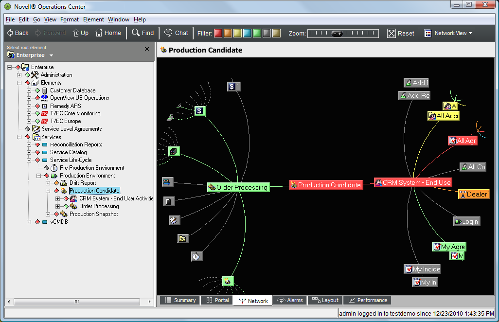
-
As the Production Candidate view is updated to reflect current status and change as they occur, compare it to the Production Snapshot baseline to identify changes.
12.1.2 PART 1: Set Up a Production Candidate
This section assumes you are familiar with the Service Configuration Editor. For descriptions of all the steps required to define a service configuration definition, see Section 8.3, Creating Service Configuration Definitions.
To set up a production candidate:
-
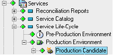
In the Explorer pane, create an element that is the parent of the new tree.
In this example, the new element is named Production Candidate:
-
Right-click the element, then select Service Configuration > Create to open the Service Configuration Editor.
-
To define the Structures for the element by identifying an existing hierarchy that drives the shape of the new tree, create a Structure definition that adds the Service Catalog element as the Structure Root.
The Service Catalog hierarchy contains a series of elements that represent key services.
-
To see all elements contained in the Service Catalog hierarchy, leave Starting Depth and Ending Depth at 0.
-
Use the default Matching Rule to apply a simple name match to select elements.
For more information on Matching Rules, see Creating a Matching Rule.
-
Define the Sources for the configuration by identifying an existing hierarchy that provides state and information to the new elements in the configuration.
In doing this, create a Source definition that uses the Hosts branch of the Tivoli T/EC adapter.
For more information on defining sources, see Section 8.3.3, STEP 3: Define Sources.
-
Use the default join rule to link state information to structure elements using a simple name match.
This definition allows state and property information to be available for any new elements found when the configuration searches for dependencies.
For more information on join rules, see Using Join Rules.
-
To define Dependencies for the configuration by specifying dependency rules to apply to a related hierarchy:
-
Create a Dependency Consumer definition, then select the By Network branch of a discovery Adapter to be the Dependency Root, as shown in the following illustration:
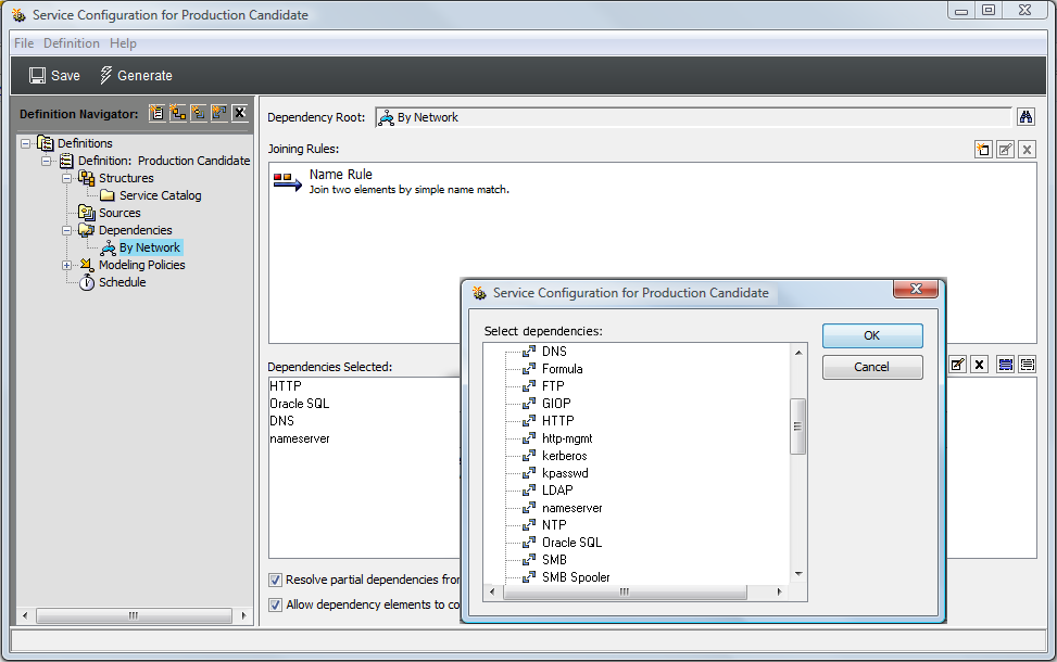
For more information on creating dependencies, see Section 8.3.4, STEP 4: Define Relationship Dependencies.
-
Use the default join rule to link discovered elements to structure elements using a simple name match.
The By Network hierarchy is from a discovery tool adapter that has run discovery on networks. It contains listings of servers and applications organized by network.
-
-
Browse and select Dependency Types as shown in the illustration in Step 8.
The selected dependencies along with the join rules select the information for the new configuration.
-
To define Generation and Correlation policy rules to further define how the configuration is generated and elements are correlated:
-
In the left pane, expand Modeling Policies, then click Generation or Correlation.
The right pane updates.
For more information on Generation, see STEP 5: Select Generation Options.
-
To create a link to source branches where matches occur (displays source elements as children), select the Display Source Elements As Children check box.
-
If you do not want to include source information from the Tivoli T/EC adapter for structure elements (in this case, sources provide state to the new objects discovered from the search for dependencies), select the Copy Properties from Structure Elements and/or Create State Relationship to Structure Elements check boxes.
-
Retain Correlation defaults to correlate configuration objects using a basic Static Match.
Those objects that are matched are included in the new configuration tree.
For more information on Correlation, see STEP 6: Select Element Correlation Options.
-
-
Click Save on the toolbar to save configuration settings.
-
Click Generate on the toolbar to generate the new tree.
-
After the configuration is run and results are verified, create a schedule for the generation of the service configuration on a routine basis.
For an up-to-date view of the network, schedule this configuration to update every 5 minutes.
12.1.3 PART 2: Set Up the Production Snapshot
-
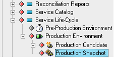
In the Explorer pane, create an element that is the parent of the new tree.
In this example, the new element is named Production Snapshot:
-
Right-click the element, then select Service Configuration > Create to open the Service Configuration Editor.
-
To define the Structures for the element by identifying an existing hierarchy that drives the shape of the new tree, create a Structure definition that adds the Production Candidate element as a Structure root, as shown in the illustration:
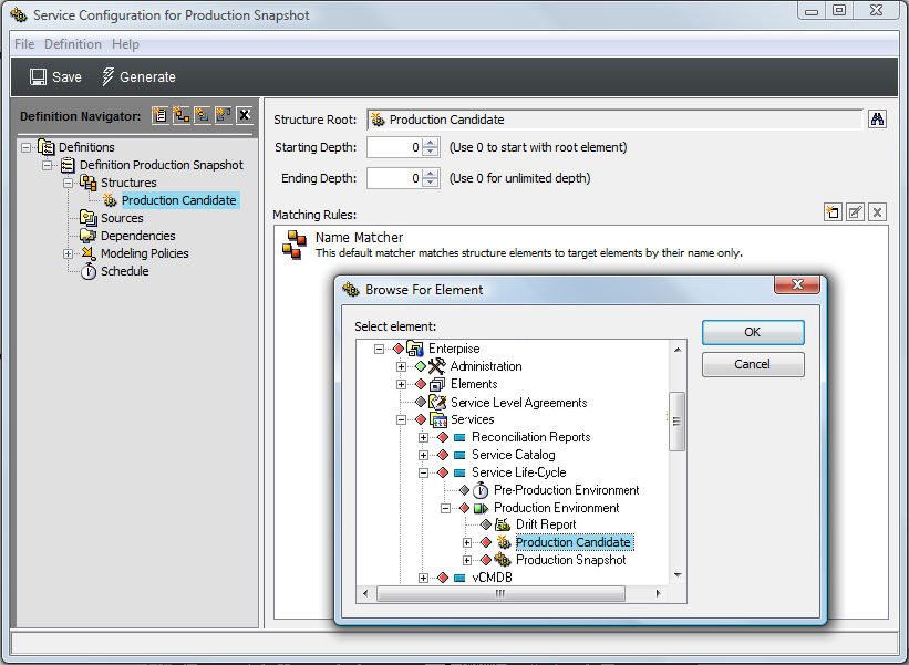
The Production Candidate hierarchy is the same view created by the configuration that was defined in PART 1: Set Up a Production Candidate of this scenario.
-
Define the Sources for the configuration by identifying an existing hierarchy that provides state and information to the new elements in the configuration.
Because this configuration is meant to be a snapshot of the Production Candidate hierarchy, it is desirable to copy the configuration as it exists. It can be assumed there is greater interest in the current state information as provided by the Structure. Instead of creating any Source definitions, use Generation policy options to capture properties and state calculations from the Structure elements.
-
To define Generation and Correlation policy rules to further define how the configuration is generated and elements are correlated:
-
In the left pane, expand Modeling Policies, then click Generation or Correlation.
The right pane updates.
-
To obtain the state directly from the structure, select the Create State Relationship to Structure Elements check box.
-
To have the hierarchy correlate directly as defined, accept the default Static Match setting in Correlation policies.
Those elements that are matched are included in the new configuration tree.
-
-
Click Save on the toolbar to save configuration settings.
-
Click Generate to generate the new tree.
The following illustration shows the Production Snapshot Network view:
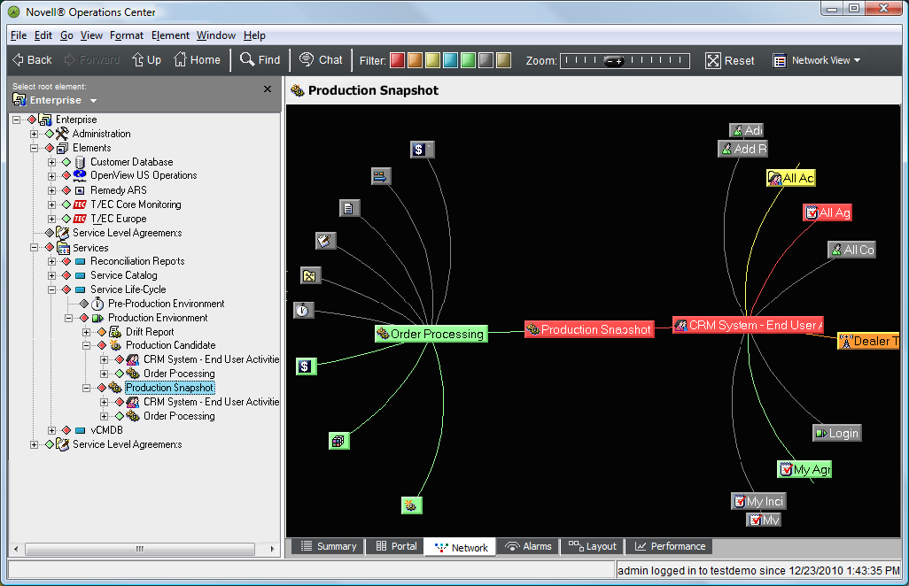
-
After the configuration is run and results are verified, create a schedule for the generation of the service configuration on a routine basis.
Because this configuration is the baseline used to compare against the Production Candidate configuration, it could be desirable to update the configuration manually when deemed necessary. A schedule is not created to update the configuration.