4.1 Monitoring Elements
The elements available to monitor depend on your access permissions.
The following topics are related to the basic monitoring of elements:
4.1.1 Understanding Adapter and Service Model Elements
In the pane, you are likely to have access to the following types of elements:
-
Adapter Elements: Elements displayed under the root element originate from adapters and are referred to as adapter elements. These elements can be linked to from the hierarchy.
-
Service Model Elements: Administrators can create or import elements in the > hierarchy. These elements can have custom property pages.
For more information about Service Model elements, see the Operations Center 5.0 Service Modeling Guide.
For information about various display options in the pane, see Section 3.0, Customizing the Console Views.
4.1.2 Understanding Element Condition
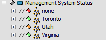
In the console, color-coded element conditions help identify critical system events. These condition indicators display for each element in the and panes. Condition indicators display as colored diamonds next to each element:
Figure 4-1 Condition Indicators in the Explorer Pane
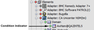
For instructions on hiding or showing the diamond condition indicators in the pane, see Section 3.1.1, Hiding or Displaying Condition Indicators.
Condition indicators also display in:
-
The column of the pane
-
The element property pages (see Section 4.2, Viewing Element Properties)
Table 4-1 describes the standard element condition colors and their default definitions from most critical to least critical.
Table 4-1 Default Element Condition Colors
|
Color |
Element Status |
|---|---|
|
Red |
CRITICAL |
|
Orange |
MAJOR |
|
Yellow |
MINOR |
|
Blue |
INFORMATIONAL |
|
Green |
OK |
|
Gray |
UNKNOWN |
|
Brown |
UNMANAGED |
In many cases, Administrators link an element or element as a child of another element. In this case, the child to contribute to the condition of the new parent. In the pane, a linked element icon displays by these elements, indicating that the element was created elsewhere in the hierarchy and later linked to this parent using the option.
Figure 4-2 Linked Element Indicators in the Explorer Pane
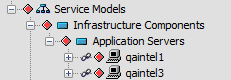
Removing the link allows the child to still display in that part of the hierarchy, but with its condition no longer affects the parent, as symbolized by the nonsource element link icon in the pane:
Figure 4-3 Nonsource Element Indicator
For more information about hiding and showing linked element indicators, see Section 3.1.2, Displaying Linked Element Indicators
For more information about hiding and showing nonsource elements indicators, see Section 3.1.3, Displaying Nonsource Element Indicators.
4.1.3 Reviewing Element Information
After selecting an element in the pane, the pane updates to display information about the selected element’s children. The information varies among views:
Understanding the Summary View
The view displays the first-level child elements of the element selected in the pane.
Figure 4-4 Summary View
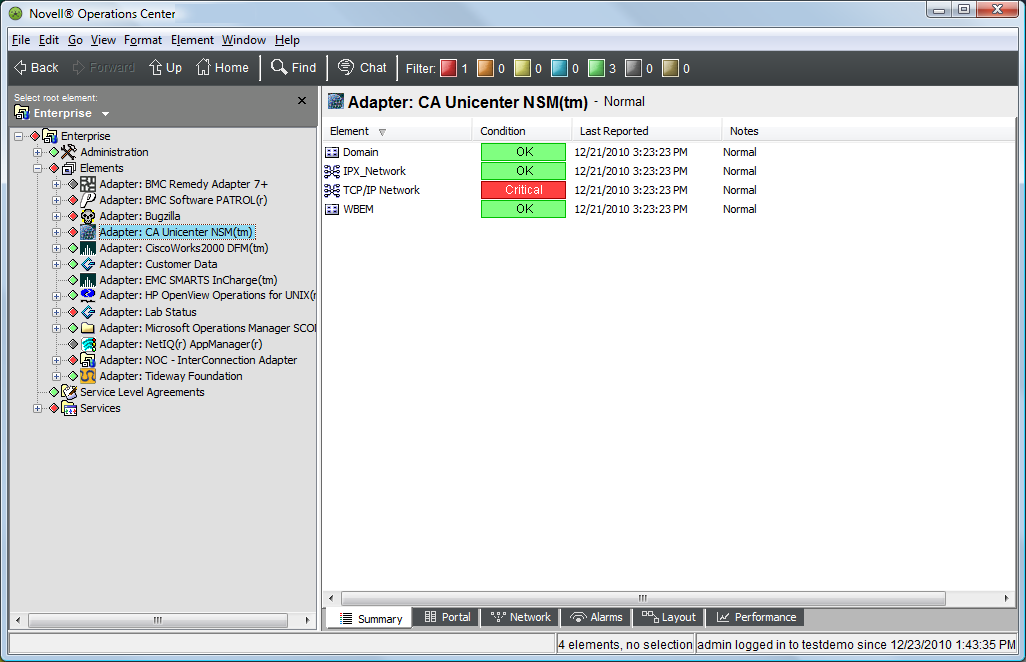
By default, it displays four informational columns, summarized in the following:
-
Element: Displays the element name.
-
Condition: Identifies the element’s current condition.
-
Last Reported: Displays the time of the most recent element condition update.
-
Notes: Provides a brief remark regarding the element’s condition.
Understanding the Network View
The view provides a graphical view of elements and their relationship to other elements within the larger infrastructure. It presents the selected element at the center of the view, with lines connected to first-level child elements. The line colors identify the condition of the child element:
Figure 4-5 Network View
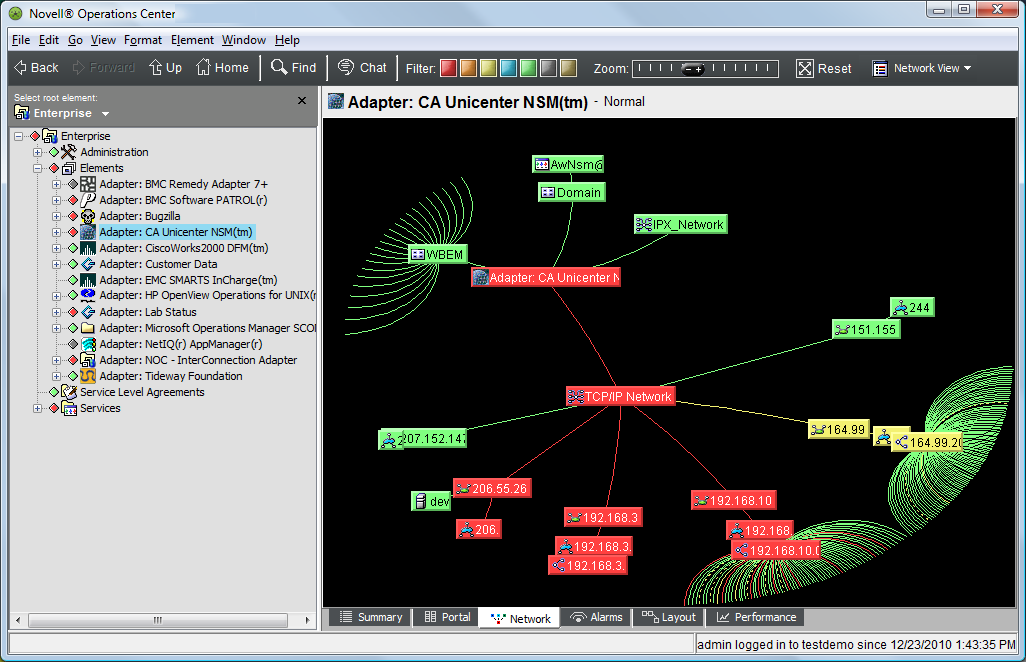
User access privileges determine which elements display in the view. The currently selected level of the element hierarchy in the pane determines whether the entire network displays, or only a portion of it.
Understanding the Layout View
The view uses icons to represent system elements and how they relate to each other:
Figure 4-6 Layout View
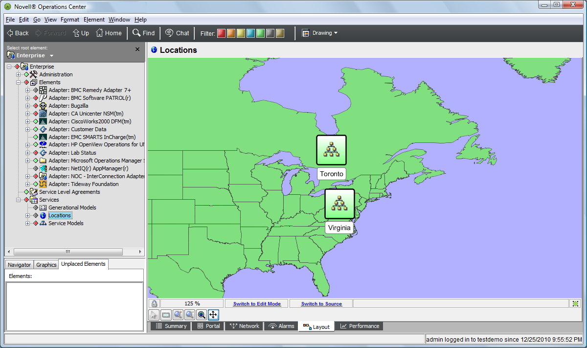
The view is available for all elements, including:
-
Services > Locations: Displays a global map. Each color-coded geographical site identifies the most severe condition among its child elements.
-
Services > Service Models: Displays icons representing any element and type of relationship among elements, such as functional organizations or processes. Customize the view using drawing tools.
For more information, see the Operations Center 5.0 Custom Drawing and Layout Guide.