3.8 Reporting the Results (Step 3)
As soon as a Diagnosis is complete, you can see a summary of the results and generate a report. For more information, see Section 5.0, Understanding Results.
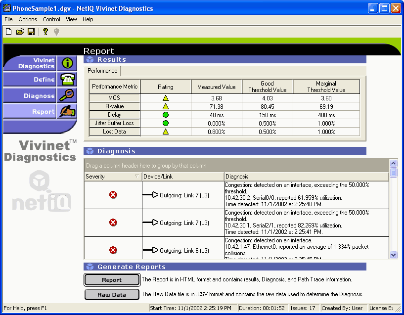
Click the Report tab to enter the Report view.
|
Report View Component |
Description |
|---|---|
|
Results table |
Summarizes the call performance results of diagnostic tests run between the endpoints or, if your Diagnosis used phones, the call performance data collected from network devices. The Mean Opinion Score (MOS) is the overall estimation of VoIP call quality between the Target Devices. The remaining data shows how the MOS was derived, based on delay, jitter buffer loss, and lost data statistics. These statistics have been compared to the thresholds configured for each VoIP performance metric. The green, yellow, or red rating icons provide an instant sense of whether performance was acceptable. Any performance metrics gathered on the network are defined only as “issues” if they conform to the thresholds you set. For more information, see Section 3.5.5, Setting Thresholds and Section 5.2.1, Interpreting the Results Table. NOTE:In a Cisco environment for which no endpoints are available in the subnets where you are performing the Diagnosis, you will receive results for, at most, “Lost Data” and “Delay.” The same is not true for a Nortel environment. Even without endpoints, RTPStatShow can provide R-value and MOS. And if the Diagnosis was launched by an R-value trap event in AppManager, you will receive all expected VoIP metrics. |
|
Diagnosis table |
Summarizes any issues found to provide a Diagnosis of the problem. The severity icons provide quick identification of problem. The issues are sorted by severity (high to low). Network problems can include major issues, minor configuration problems, unstable routing, excessive router delays, and more. All discovered issues are accompanied by an explanation. For more information, see Section 5.2.2, Interpreting the Diagnosis Table. |
|
Generate Reports |
Offers two result formats: an HTML-formatted Report, and a Raw Data file in comma-separated values (CSV) format, suitable for a spreadsheet program, such as Microsoft Excel. For more information, see Section 3.8.1, Diagnosis HTML Report and Section 3.8.2, Raw Data File. |
3.8.1 Diagnosis HTML Report
After Vivinet Diagnostics has located one or more potential problems with your VoIP implementation, you can print or view a report of the findings. You can create an HTML report or a comma-separated values (CSV) file from the Report view. For more information, see Section 3.8.2, Raw Data File.
The HTML report provides easy access to the highlights of the Diagnosis, along with details about how the Diagnosis was conducted.
The report summarizes the problem as you defined it, including the addresses or phone numbers of the Target Devices, presents a graphic depiction of the Path Trace it performed, and then lists and describes the probable sources of the problem.
To generate the HTML report:
-
In the Report view, click Report. The report is generated in HTML format so you can view it in your Web browser. You can regenerate the report at any time from a saved Diagnosis file.
-
To save the report while the report is open in your Internet Explorer browser window, click Save As on the File menu, and then choose one of the following options from the Save As Type list:
-
Save As Web page, complete to save the Web page in its original format (.htm), including all graphics and style sheet files.
-
Save As Web page, archive to save a snapshot of the current Web page in MHTML (.mht) format, including all graphics.
-
HINT:You can also generate the HTML report from a command-line interface on the Vivinet Diagnostics computer. Type the following at the prompt:
diagnostics.exe -h -v report -r html [name of diagnosis].dgv
3.8.2 Raw Data File
Although Vivinet Diagnostics contains expert-level information about the factors that affect VoIP call quality and performance, you cam perform your own analysis of the data the application has uncovered. If you want to independently analyze the data collected from your network during a Diagnosis, use the Raw Data file to gather data in a useful format.
When you click the Raw Data button, all of the data Vivinet Diagnostics used to create the report is exported to a text file in comma-separated values (CSV) format. Files in CSV format can be opened in Microsoft Excel.
HINT:Some spreadsheet programs, such as Microsoft Excel, may truncate the decimals in large numbers for display purposes. However, the actual full value is stored and used for calculations. If you suspect your spreadsheet is not displaying decimals, you can format the affected cells as “Numeric” and specify the number of decimal digits you want to display.
For more information, see the following topics:
Understanding the Raw Data File
The Vivinet Diagnostics Raw Data file is a comprehensive collection of data gathered during a particular Diagnosis. When you first take a look at a Raw Data file from a typical Diagnosis, you may have a few questions about some of the abbreviations used and what is included in the file.
The Raw Data file, with file extension .csv, is saved by default to the /My Documents folder on the local computer. Again by default, this file has the same filename as the Diagnosis it reflects. Open this file using a compatible spreadsheet program, such as Microsoft Excel. It is divided into several major sections, designated by headings in all-capital letters.
The Product Information section provides version information about the Vivinet Diagnostics Console used to run the Diagnosis. Just below that is the Diagnosis Summary, with information about when the Diagnosis was run, the number of network issues it found, and any voice gateways discovered on the network.
Next is information about Diagnosis Configuration, divided into subsections:
|
Subsection |
Description |
|---|---|
|
CallManagers |
Lists the IP addresses or DNS hostnames of the Cisco CallManagers you added or that were discovered by Vivinet Diagnostics. |
|
Call Servers |
Lists the IP addresses of the Nortel Call Servers involved in the Diagnosis. |
|
Signaling Servers |
Lists the IP addresses of the Nortel Signaling Servers involved in the Diagnosis. |
|
Firewall Port |
Lists the port you designated for diagnostic traffic sent between the endpoints through a firewall. |
|
Call Script |
Provides the name of the call script (codec) used and indicates how call script parameters were set. NOTE:Very infrequently, the codec indicated in the Call Script section does not match the codec identified in the Quality Stats section. The Quality Stats section identifies the codec in use in your environment. If that codec is not supported, Vivinet Diagnostics uses G.711u to drive VoIP traffic. G.711u mimics the traffic behavior of the known unsupported codecs. For more information, see Section 4.2.2, Reviewing Codecs. |
|
QoS |
Reports whether QoS was applied and what bit settings were used. |
|
Thresholds |
Shows all the thresholds configured for a Diagnosis. |
The Problem Definition section lists the device type (endpoints, phones, or other — such as gateways and routers), each Target Device’s IP address or DNS hostname, the time the problem occurred, and, if endpoints were the Target Devices, the call script used for the simulated VoIP performance test traffic.
The last sections contain the Results and the Quality Stats. First, the results from VoIP performance tests are shown, including what was measured for each performance metric (MOS, R-value, Delay, Lost Data, and Jitter Buffer Loss), the severity rating of each measurement (such as “Marginal” or “Poor”), and the configured values for both Good and Marginal thresholds.
Next, the quality statistics for any Nortel devices are shown, followed by the addresses of any voice gateways discovered on the network during the Diagnosis are provided. And finally, raw results summarizing all the objects found in the path and their statistics are shown. For more information, see Field Definitions for the Raw Data File.
Within the Raw Data file, the following relationships organize the data objects you see:
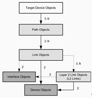
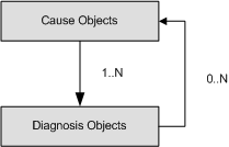
The drawing shows that the Target Device Objects are treated as parents to all other object types. “Path Objects” define Path Traces that are generated whenever a Diagnosis is run and depicted graphically in the Diagnose view. They are owned by the two Target Devices whose VoIP data path they define. Numbers in the drawing above indicate the number of objects contained by each parent object. Furthermore, all Diagnoses contain 0 to N Diagnosis objects, 0 to N Stat (statistic) objects, and 0 to N Cause objects. All Cause objects must have at least one Diagnosis object.
All Vivinet Diagnostics objects, such as the two Target Devices you specified when you defined the problem on your network, are assigned an object ID number. Along with other statistics pertaining to an object, that object’s parent in the containment hierarchy is also indicated. The Target Devices are always assigned object IDs 1 and 2. So, for example, the endpoint named Device 1 (the first Target Device specified) with object ID 1 might be shown to have a parent link with object ID 5.
Field Definitions for the Raw Data File
The following table defines some of the unfamiliar fields in the Raw Data file.
For more information about what is shown in the CSV file, see the following related topics.
|
Field |
Definition |
|---|---|
|
ATM Objects |
Owned by interface objects. Relevant properties are defined as follows:
|
|
Call Objects |
A single Cisco CallManager Call Detail Record representing information about a single VoIP call. For more information, see Phone Call Details Tab. |
|
Cause Objects |
The Probable Causes of issues flagged on the network during a Diagnosis. Relevant properties are defined as follows:
For more information, see Probable Cause Definitions. |
|
CCME Devices |
Devices for Cisco CallManager Express, also known as Unified Communications Manager Express |
|
CCME Phones |
Phones registered to Cisco CallManager Express devices |
|
Device Objects |
A router, a voice gateway, or a switch. For more information, see Section 5.1.5, Router Properties and Section 5.1.6, Switch Properties. |
|
Diagnosis Objects |
A diagnostic response to issues flagged on the network during a Diagnosis. Relevant properties are defined as follows:
For more information, see Section 5.2.2, Interpreting the Diagnosis Table. |
|
Ethernet Objects |
An Ethernet-enabled router or switch interface owned by interface objects. Relevant properties are defined as follows:
|
|
Frame Relay Objects |
Owned by interface objects. Relevant properties are defined as follows:
|
|
GW Call Level Objects |
Statistics from the voice gateway for recent POTS call legs |
|
GW Call Objects |
Statistics from the voice gateway for active POYTS and VoIP call legs |
|
GW Call Stat Objects |
Statistics from the voice gateway for recent VoIP call legs |
|
Interface Objects |
A router or switch interface owned by a link object or a Layer 2 link (L2 link) object. It may own Ethernet objects. Relevant properties are defined as follows.
Properties not defined here are defined in the ATM Objects definition. Other properties are stat objects and are described in Section B.0, Statistics Used in Diagnoses. |
|
Link Objects |
Defined by router interfaces. Vivinet Diagnostics finds links by running traceroute tests. The name property is derived from the resolved DNS hostname of the egress interface. For more information, see Section 5.1.2, Link Properties. |
|
L2 Link Objects |
Defined by switch interfaces functioning at Layer 2 of the OSI (Open System Interconnection) Model. Some router interfaces may also function at Layer 2. For more information, see Section 5.1.2, Link Properties. |
|
Path Objects |
Defines the Path Trace generated for a Diagnosis. Every Diagnosis has two path objects because the Path Trace can be shown from either direction between the two Target Devices. For more information, see Section 5.1, Reviewing Path Trace Components. |
|
Phone Objects |
Telephone used as Target Device in the Diagnosis. Parent of Path Objects. May be either an IP phone or a POTS phone. For more information, see Section 5.1.4, Phone Properties. |
|
RTP Objects |
Values gathered by Nortel RTCP-XR or RTCP. Relevant properties are defined as follows:
|
|
RTP Objects |
Properties not defined here are defined in Phone Quality Stats Tab. For more information, see Section 5.3.1, Burst Density and Section 5.3.9, R-value. |
|
Serial Objects |
Represent the basic Layer 2 “serial” interfaces for certain WAN links |
|
Stat Objects |
A type of statistic gathered by Vivinet Diagnostics during a Diagnosis. Relevant properties are defined as follows:
For more information, see Section B.0, Statistics Used in Diagnoses. |
|
Target Objects |
Devices selected as Target Devices. For more information, see Section 5.1.1, Endpoint Properties and Section 3.6, Defining the Problem (Step 1). |
|
Traffic Class Objects |
Details about the traffic classes defined on Cisco devices |
|
Voice Analog Objects |
Details about the POTS interfaces used for voice traffic |
|
Voice Dial Peer Objects |
POTS dial peer definitions for a voice gateway |
|
Voice Digital Objects |
Details about the VoIP interfaces used for voice traffic |
|
VoIP Dial Peer Objects |
VoIP dial peer definitions for a voice gateway |