1.7 Configuring Communication Manager To Send RTCP Packets and CDRs
Several Knowledge Scripts need Communication Manager to send RTCP (Real-time Transport Control Protocol) packets and call detail records (CDRs) to the AppManager agent on the proxy computer:
-
CallActivity, which needs both RTCP packets and CDRs
-
CallFailures, which needs CDRs
-
CallQuality, which needs RTCP packets
-
CallQuery, which needs CDRs
-
PhoneQuality, which needs RTCP packets
If RTCP packets and CDRs are not sent to the AppManager agent, these scripts cannot collect data or raise threshold-crossing events.
Use the Communication Manager System Administrator Terminal (SAT) to configure RTCP packets and CDRs. Commands for this screen-based terminal application generally start with a verb such as “display,” “list,” and “change.” In the following topics, use “change” commands to implement the RTCP and CDR configuration. The procedures in these topics assume you know how to navigate in SAT.
1.7.1 Step 1: Configuring IP Address and Port for RTCP Packets
Use the IP-Options System Parameters screen to configure the IP address and port to which Avaya IP phones will send RTCP packets. To access this screen, execute the following command: change system-parameters ip-options
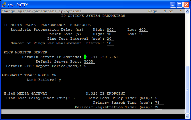
Complete the fields on the screen according to the information in the following table. Press [Esc + E] to save your changes and return to the command line.
|
Field |
Description |
|---|---|
|
Default Server IP Address |
Type the IP address of the computer acting as proxy for Communication Manager servers. Avaya IP phones must be able to send RTCP packets to this computer. Any firewall between the phones and the proxy computer must be configured to allow UDP packets to flow through it in the direction from phones to proxy computer. |
|
Default Server Port |
Type the UDP port number on the proxy computer to which Avaya IP phones send RTCP packets. The default port number is 5005. You can change it to any other valid port number, but remember that RTCP specifications require an odd, not even, port number. NOTE:For each Communication Manager being monitored by the proxy computer, you must specify a different UDP port number here. AppManager uses the port number to determine which RTCP packets belong to a given Communication Manager. For more information, see Configuring Unique Port Numbers for Multiple Communication Managers. |
|
Default RTCP Report Period |
Use this field to specify the frequency with which Avaya IP phones send RTCP packets to the proxy computer. The default is every 30 seconds. Valid values are between 5 and 30. Important concepts
|
1.7.2 Step 2: Changing or Disabling RTCP Per IP Network Region
All Avaya IP phones belong to a particular IP network region, which is a set of IP address ranges. By default, the phones associated with a region send RTCP packets to the server specified in Step 1: Configuring IP Address and Port for RTCP Packets. However, you can specify that phones associated with a particular IP network region send their RTCP packets to a different server, with even a different frequency, or you can disable the sending mechanism altogether.
Use the IP Network Region screen to change a region’s RTCP configuration. To access this screen, execute the following command: change ip-network-region region number]
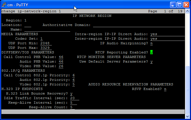
Complete the fields on the screen according to the information in the following table. Press [Esc + E] to save your changes and return to the command line.
|
Field |
Description |
|---|---|
|
RTCP Reporting Enabled? |
Set to y to enable RTCP reporting. Set to n to disable the RTCP reporting mechanism altogether. |
|
Use Default Server Parameters? |
Set to y to use the values specified in Step 1: Configuring IP Address and Port for RTCP Packets. Set to n to use different values. If you set to n, press [Esc + E] to save your changes. Then execute the change ip-network-region [region number] command again. New fields are displayed on the screen.
|
1.7.3 Step 3: Assigning a Node Name to the Proxy Agent Computer
Assign a node name to the proxy agent computer’s IP address. The node name enables Communication Manager to recognize the proxy agent computer and send CDRs to it.
Use the IP Node Names screen to assign a node name to the proxy agent computer’s IP address. To access this screen, execute the following command: change node-names ip
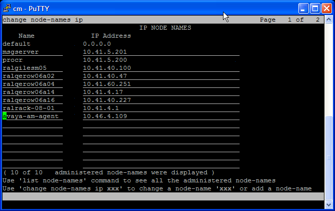
Complete the fields on the screen according to the information in the following table. Press [Esc + E] to save your changes and return to the command line.
|
Field |
Description |
|---|---|
|
Name |
Navigate to an empty Name field and type the host name of the proxy computer. |
|
IP Address |
In the associated IP Address field, type the IP address of the proxy computer. |
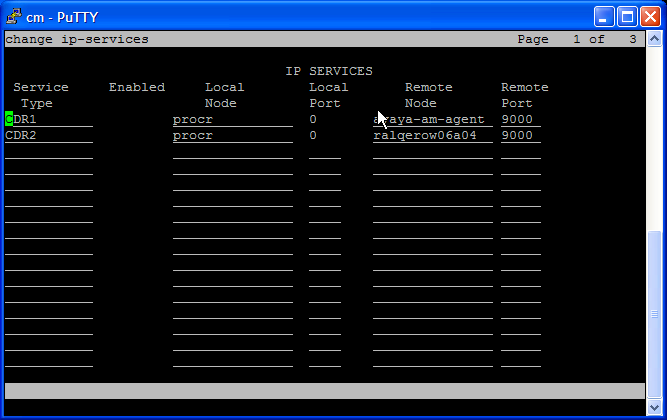
1.7.4 Step 4: Defining the CDR Link to the Proxy Agent Computer
Communication Manager can send CDRs to one or two endpoint computers (or recipients; not to be confused with NetIQ Performance Endpoints): CDR1 and CDR2. You need to define the link between these endpoint computers and the proxy agent computer.
NOTE:
-
One of the endpoint computers must be the proxy agent computer.
-
You configure the format of the endpoint computers in Step 5: Configuring CDR Endpoints and Format.
Use the IP Services screen to associate CDR1 or CDR2. To access this screen, execute the following command: change ip-services
Complete the fields on the screen according to the information in the following table. Press [Esc + E] to save your changes and return to the command line.
|
Field |
Description |
|---|---|
|
Service Type |
Type CDR1 or CDR2, as appropriate. |
|
Local Node |
Type procr. |
|
Local Port |
Type 0. |
|
Remote Node |
Type the node name you assigned in Step 3: Assigning a Node Name to the Proxy Agent Computer. |
|
Remote Port |
Type the TCP port number to which CDRs will be sent on the proxy agent computer. Notes
|
1.7.5 Step 5: Configuring CDR Endpoints and Format
The CDR format can be different for each endpoint computer. Communication Manager offers several predefined formats and allows for the creation of a custom format. The CDRs sent to the AppManager agent on the proxy computer need a custom format.
NOTE:If CDR1 is formatted for a billing system, the formatting procedure is different. For more information, see Step 7 (Optional): Configuring CDR Format if CDR1 is Formatted For a Billing System.
Use the CDR System Parameters screen to assign an endpoint and to configure CDR format. To access this screen, execute the following command: change system-parameters cdr
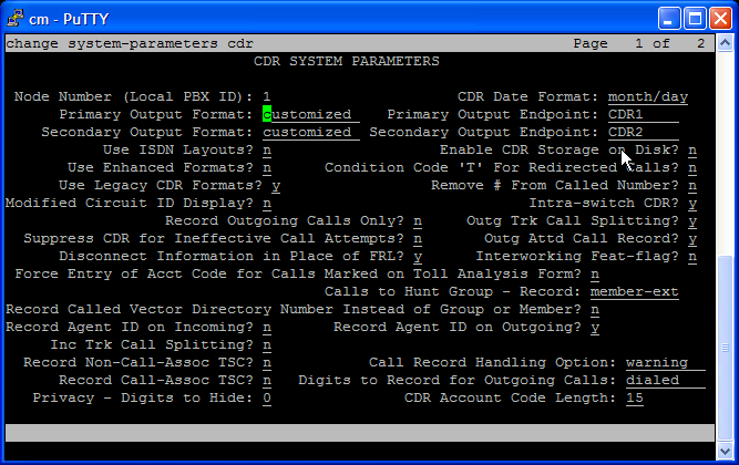
Use the Primary Output fields to configure one set of endpoint information and the Secondary Output fields to configure the other. The following table provides directions for configuring Primary Output; the process is the same for configuring Secondary Output.
|
Field |
Description |
|---|---|
|
Primary Output Format |
Type customized. |
|
Primary Output Endpoint |
Type CDR1 or CDR2. Use the label that is not being used by the Secondary Output Endpoint field. |
|
Intra-switch CDR? |
Set to y to ensure that a CDR contains all calls between two phones. If you set this field to n, a CDR will contain data about incoming and outgoing calls, but no data about internal calls. If you set this field to y, also specify the phone extensions for which intra-switch CDRs will be created. For more information, see Step 8 (Optional): Specifying Intra-Switch Extension Numbers. |
|
Suppress CDR for Ineffective Call Attempts? |
Set to n to ensure CDRs contain information about failed calls. If you set this field to y, CDRs contain only data about successful calls and the CallFailures script will have no data to retrieve. |
Press [Esc + N] to navigate to the next page of the screen.
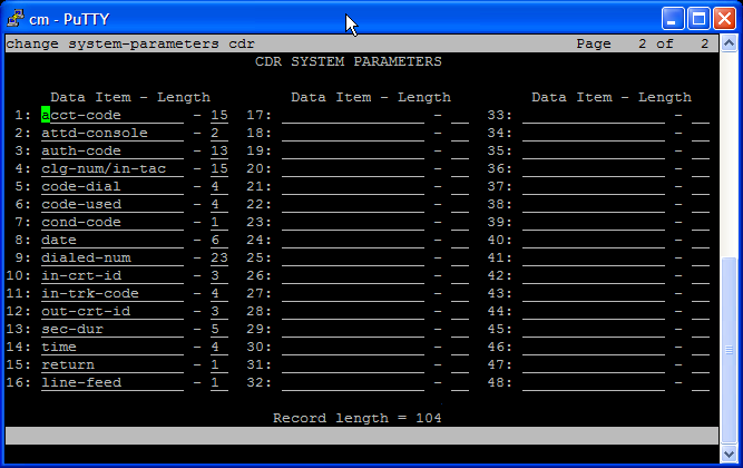
Use the fields on this page to customize the CDR format. In rows 1 through 16, type the Data Item and Length values as indicated in the following table. Press [Esc + E] to save your changes and return to the command line.
|
Row |
Data Item |
Length |
|---|---|---|
|
1 |
acct-code |
15 |
|
2 |
attd-console |
2 |
|
3 |
auth-code |
13 |
|
4 |
clg-num/in-tac |
15 |
|
5 |
code-dial |
4 |
|
6 |
code-used |
4 |
|
7 |
cond-code |
1 |
|
8 |
date |
6 |
|
9 |
dialed-num |
23 |
|
10 |
in-crt-id |
3 |
|
11 |
in-trk-code |
4 |
|
12 |
out-crt-id |
3 |
|
13 |
sec-dur |
5 |
|
14 |
time |
4 |
|
15 |
return |
1 |
|
16 |
line-feed |
1 |
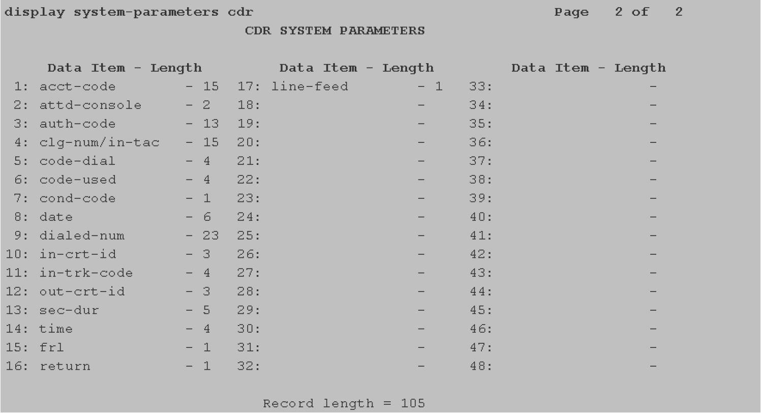
1.7.6 Step 6 (Optional): Configuring CDR Parameters to Filter by FRL Codes
If you want to filter by some or all of the Facilities Restriction Level (FRL) codes, you can provide a comma-separated list of the codes you want to filter by for the Include only these FRL codes parameter of the CallFailures Knowledge Script.
To avoid an error message, run the SetupSupplementalDB Knowledge Script once before running CallFailures. Also, set up FRL at the Avaya System Access Terminal (SAT) interface before running this script, and do not use FRL at the Avaya SAT interface with previous versions of this module.
To set up FRL filtering:
-
To access the CDR System Parameters screen, execute the following command: change system-parameters cdr
-
Press [Esc + N] to navigate to the next page of the CDR System Parameters screen.
-
Complete rows 1-14 with the same values as those in step 5.
-
In row 15, specify frl as the data item and 1 as the length.
-
In row 16, specify return as the data item and 1 as the length
-
In row 17, specify line-feed as the data item and 1 as the length.
-
Press [Esc + E] to save your changes and return to the command line.
1.7.8 Step 8 (Optional): Specifying Intra-Switch Extension Numbers
If you enabled intra-switch CDRs in Step 5: Configuring CDR Endpoints and Format, specify the phone extension numbers for which you want intra-switch CDRs.
Use the Intra-Switch CDR screen to specify extension numbers. To access this screen, execute the following command: change intra-switch-cdr
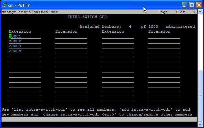
In the Extension columns, type one extension number per line.
Press [Esc + E] to save your changes and return to the command line.