12.4 Reconciliation
Assume you have correlated views to gain visibility into your environment. What is the next step? It might be useful to see what might not be integrated in the tree. Use discovery tools to determine what is over or under managed.
Figure 12-2 illustrates a view which displays elements that are not integrated in the SCM tree:
Figure 12-2 Network View
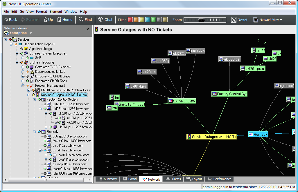
12.4.1 Scenario Description: Show Critical Services (Outages) with No Matching Trouble Tickets
In this example, the goal is to build a view that shows critical services (outages) that do not have matching trouble tickets.
Using SCM, tickets are matched to the services by using a simple hostname match. Only those services without matches are included (an inverse match).
The resulting hierarchy shows all critical services without an associated trouble ticket.
This scenario uses:
-
A custom Data Integrator adapter that pulls in database information about IT services and the technology that supports them
-
A Remedy ARS adapter that provides trouble ticket information
To use SCM to identify service outages without an associated trouble ticket:
-
Add an element that is the parent of the new tree.
In this example, the element is created under the element:

-
Right-click the element, then select > to open the Service Configuration Editor.
-
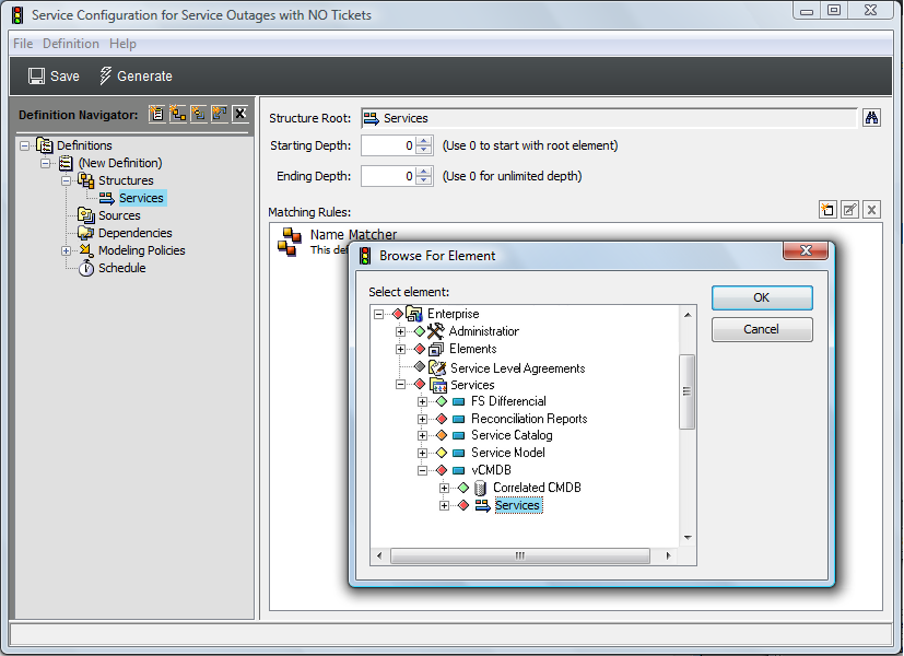
To define the Structures for the element by identifying an existing hierarchy that drives the shape of the new tree, create a Structure definition that adds the element as a , as shown in the illustration below.
is a hierarchy created by a Data Integrator adapter that pulls in database information about IT services and the technology that supports them.
-
To see all elements contained in the hierarchy, leave and at O.
Only outages (elements that are down) without an associated trouble ticket should display.
-
Define a Matching Rule that uses an expression (condition=CRITICAL) to replicate only those structure elements that have a CRITICAL condition level.

-
To define the Sources for the configuration by identifying an existing hierarchy that provides state and information to the new elements in the configuration, create a Source definition that adds the element as the .
is a hierarchy from a Remedy ARS adapter integration. It provides trouble ticket information to the new configuration elements based on a join rule using a simple name match.

-
To define and policy rules to further define how the configuration is generated and elements are correlated:
-
To use elements found in the tree to populate the new configuration tree, select the check box in policies.
-
To carry over state and properties from elements, select the and check boxes in policies.
-
To view service outages without tickets, we will want to specify that the configuration show only those services that do not have matching trouble tickets.
For the policy, select the radio button to pick up only the elements without matching trouble tickets.
-
-
(Optional) Define scripts to apply to configuration elements after generation.
In the left pane, click , select the check box, then enter the script directly in the text area provided.
Because this configuration looks for service outages without associated trouble tickets, it could be very useful to then use the configuration to automatically generate a trouble ticket. In this scenario, we use the scripting feature to activate a script that dynamically creates a trouble ticket for services that do not have an existing trouble ticket as shown in the following illustration:

For information on scripting, see the Operations Center 5.6 Scripting Guide.
-
Click Save to save configuration settings, then click Generate to generate the new tree.
In this instance, elements displayed with state/condition are no longer considered outages after the configuration was generated.

-
After the configuration is run and results are verified, create a schedule for the generation of the service configuration on a routine basis.
In this case, schedule the configuration to generate every 5 minutes, as it is critical to identify outages that are not being managed properly.
For information on defining the schedule, see Section 8.3.9, STEP 9: Test and Generate the Configuration.
12.4.2 Scenario Description: Show Critical Hosts Only
A scenario similar to the previous one involves selecting specific information from multiple hosts in different geographic locations.
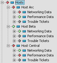
Assume there is a correlated list of hosts, as shown in Figure 12-3. Each host has the following folders:
-
Networking: Links to an adapter with networking alarm data
-
Performance: Links to an adapter with performance metric data
-
Trouble Tickets: Links to a trouble ticket system adapter
Figure 12-3 Correlated Hosts Hierarchy
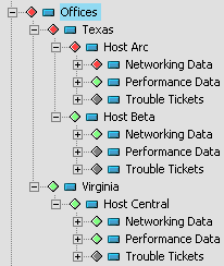
Assume there is also a geographic correlation hierarchy that shows the hosts located in two different offices, Texas and Virginia, as shown in Figure 12-4:
Figure 12-4 Element hierarchy showing hosts in two office locations
Assume you want to create an element hierarchy named , which shows only the hosts that have a CRITICAL condition. The hosts can be in either the Texas or Virginia office. The list changes over time, as host conditions change.
Using the previous scenario as a model, to create a configuration that shows only CRITICAL hosts:
-
In the Explorer pane, add an element that is the parent of the new tree.
In this example, the element is created under the element.
-
Right-click the element, then select > to open the Service Configuration Editor.
-
To define the Structures for the element by identifying an existing hierarchy that drives the shape of the new tree:
-
Create a Structure definition that adds the element as a .
-
To display the elements contained in the hierarchy, starting with the office location names, which are 1 level beneath the root, enter 1 in the field and leave at O.
-
Because the new configuration should contain only those elements that are in a CRITICAL state, define a Matching Rule that uses an expression (condition=CRITICAL) to replicate only those structure elements that have a CRITICAL condition level.

-
-
To define the Sources for the configuration by identifying an existing hierarchy that provides state and information to the new elements in the configuration, create a Source definition that adds the element as the .
is a hierarchy that lists hosts by office location. Use the default join rule for a simple name match.
-
To define and policy rules to further define how the configuration is generated and elements are correlated:
-
To use elements found in the tree to populate the new configuration tree, select the check box in policies.
-
To carry over state and properties from elements, select the and check boxes in policies.
-
To display all elements that meet the , , and other rules, leave > policy.
-
-
Click Save to save configuration settings, then click Generate to generate the new tree.
The following illustration shows the generated hierarchy, which displays only those host elements with a conditon of CRITICAL, using the location structure of the existing element hierarchy:

-
Expand the hosts to identify the CRITICAL elements that contribute to the host condition.