5.6 Rendering and Exploring Relationships

5.6.1 Understanding Element Relationships

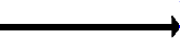
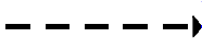
The Network view diagram distinguishes between standard parent/child relationships and linked relationships that can occur between elements by displaying different connector styles. Table 5-8 describes the connector styles and the corresponding relationship types.

Table 5-8 Connector Styles

Connector Type

Definition

Basic parent-child connector. One element is a natural child of the other element, meaning it was created directly under its parent. This occurs most often in relationships between elements under the Elements root element.

Linked parent-child connector. One element is a linked child of the other element. This occurs in the Services hierarchy when a child element is linked using the Link option. It contributes to the condition of the linked parent.

Dependency connector. One element is dependent on the other element. This occurs when dependency relationship information is available, mostly through the use of Discovery Tools.

For information about the discovery tools that Operations Center supports, see the Operations Center Adapter and Integration Guide.

5.6.2 Viewing Relationships and Dependancies

The diagram expands to display additional elements. Based on the relationship types selected, connectors and nodes display to depict the additional relationships.

To view additional relationships:

  1. Right-click an element and select:

    • Isolate: Select Full to display only the element and its parent. Select Partial to display the entire branch leading to the element.

    • Expand > Children: Select this check box to display the element’s children in the view.

    • Explore Dependencies Opens the Explore Dependencies dialog box so you can view an element’s dependencies on other elements.

  2. Right-click a connector and select Properties to view information showing how the two elements are linked.

Dependency relationships connectors display in blue with labels to show the relationship type, as shown in the previous table and illustration.

HINT:Use the element right-click Navigate Relationships option to quickly view an element’s dependency relationships and navigate to one of the end-point elements named in a relationship. For more information, see Analyzing Dependencies in the Operations Center Service Modeling Guide.

5.6.3 Exploring Dependency Relationships

A minimum of View security privileges to both the origin and end point elements in a relationship is required, or else the relationship is not displayed in the Explore Dependencies dialog box. For more information on element security privileges, see the Operations Center Security Management Guide.

To explore dependencies:

  1. In the Network view, right-click the element node, then select Explore Dependencies.

  2. In the Explore Dependencies dialog box, select a dependency.

    Dependency information displays in the right pane.