6.1 Understanding the Node Style and the Node Style Library
Operations Center ships with many different node styles. It’s easy to change the node style used in a drawing. Simply drag and drop a node style from the pane to an element in the drawing.
A dynamic node style is shaded using the current condition color of an element and displays text that represents the element name, as illustrated in Figure 6-1:
Figure 6-1 The Default Node Style Updates Automatically with Current Condition Color
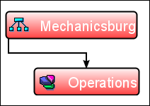
The fill color and text name change automatically when the linked element is updated. For example, in Figure 6-1, the Clean Bubble node style is bound to the element. If the element changes from CRITICAL to OK, the fill color changes from red to green.
All node styles shipped with Operations Center are dynamic. Just drag and drop a node style on an element and it uses the element name and condition color.
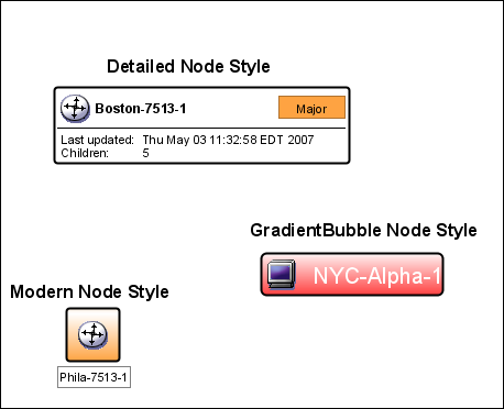
Figure 6-2 shows some of the standard node styles:
Figure 6-2 Node Style Sample
The node styles display under > > . Click a node style and a sample drawing representing the node style displays in the Layout view.
A popular node style is the Stoplight, which uses a red, yellow, or green “light” to identify the status of a linked element. For example, a red light indicates an element has a CRITICAL or MAJOR severity, as illustrated in Figure 6-3:
Figure 6-3 Layout View – Stoplight Node Style
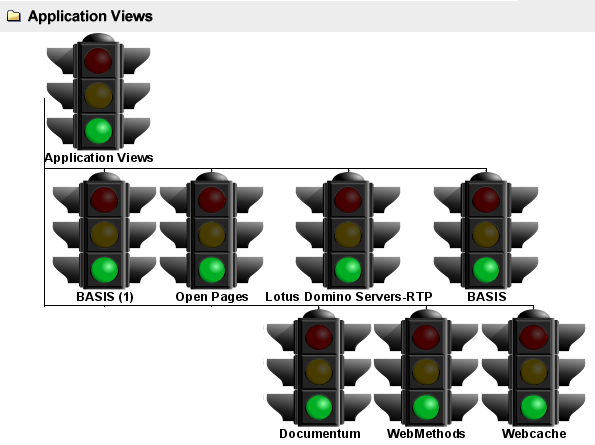
The seven severity levels used in Operations Center map to one of the three colored lights in the Stoplight node style, as defined in Table 6-1:
Table 6-1 Stoplight Node Style Color Mapping
|
Element Severity |
Stoplight Color |
|---|---|
|
CRITICAL, MAJOR |
Red |
|
MINOR, INFO |
Yellow |
|
OK, UNKNOWN, UNMANAGED |
Green |
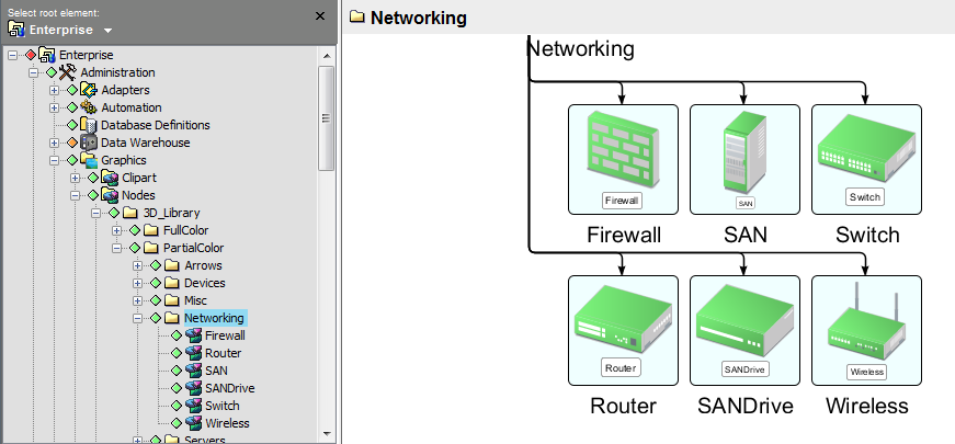
Figure 6-1 illustrates some of the node styles that are available under the folder.
Figure 6-4 3D, Partial-Filled Node Styles
You can change the node style for all elements in a drawing, for a specific element, or for all elements of a class.