13.1 Identifying Unmanaged Services
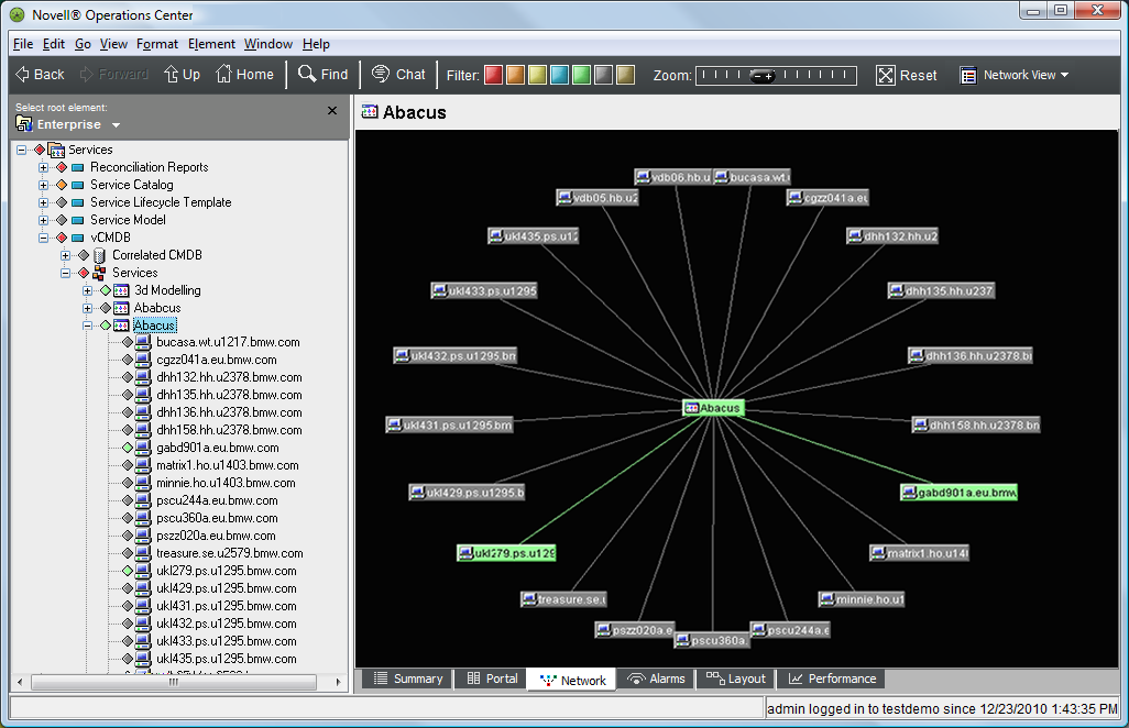
Use SCM to identify services that are unmanaged. By creating a SCM definition that links all sources to your services, it becomes obvious which services are not managed. These services display a gray or UNMANAGED condition state, as shown in Figure 13-1:
Figure 13-1 Network View: Services that are not being managed have a gray (unmanaged) condition state.
The following section steps through an example of how SCM is set up to identify services that are not managed in a network.
13.1.1 Scenario Description: View All Services That are Not Managed
In this example, a basic view of services and the technology that supports them is created. Then, services that are not being managed are identified.
SCM leverages two T/EC adapters and one HP OpenView adapter, to feed source information to a hierarchy. Data matches the services using a simple hostname match. The resulting hierarchy shows services with state information. Services that have an UNKNOWN or UNMANAGED state are identified as undermanaged.
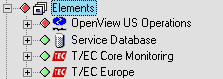
Figure 13-2 Elements Tree View
This scenario uses:
-
A custom Data Integrator adapter that pulls in database information about IT services and the technology that supports them
-
Two Tivoli T/EC Adapters that provide state information about related technology
-
An HP OpenView Network Node Manager Adapter that provides state information about related technology
13.1.2 Scenario Steps
To use SCM to identify services that are not under management:
-
In the Explorer pane, add an element that is the parent of the new tree.
-
Right-click the element, then select > to open the Service Configuration Editor.
-
To define the Structures for the element by identifying an existing hierarchy that drives the shape of the new tree, create a Structure definition that adds the element as a , as shown in the following illustration:

is a hierarchy that is created by a Data Integrator adapter that pulls in database information about IT services and the technology that supports them.
-
To define the Sources for the configuration by identifying an existing hierarchy that provides state and information to the new elements in the configuration:
-
For this example, add two Source definitions that specify Hosts from T/EC adapters as the element:

is a hierarchy from a T/EC adapter integration. It provides source information to the new configuration elements based on a simple name join.
-
Also add a Source definition that uses OpenView US Operations (an HP OpenView adapter) as a element:

-
-
Define and policy rules to further define how the configuration is generated and elements are correlated.
In this scenario, default and modeling policies are sufficient to generate the configuration tree as required.
The default Static Match correlation allows elements and information to match as specified within the Structure and Source definitions.
-
Click Save to save configuration settings.
-
Click Generate to generate the new tree.
Looking at the new tree, it is easy to identify services that do not have any related technology monitoring them. These are the services that are undermanaged (gray state).

-
After the configuration is run and results are verified, create a schedule for the generation of the service configuration on a routine basis.
In this case, run the report manually on an ad‑hoc basis when there is demand for asset and instrumentation coverage.