6.6 Using Layout Rendering Features
The Relationship browser can render a hierarchy using the following layout styles:
Table 6-4 Relationship Browser Layout Rendering Options
|
Layout Style |
Renders… |
|
|---|---|---|
|
Tree |

|
A tree-like structure with variations. Select from tree layout styles including: , , , and . For more information, see Tree Layout. |
|
Circular |

|
An interconnected ring or star topology. Layout emphasizes group structures within a network. It creates node partitions by analyzing the connectivity structure of the network, and arranging the partitions as separate circles. The circles are arranged in a radial tree layout. Select from circular layout styles including: , , and . For more information, see Circular Layout. |
|
Orthogonal |

|
Members of a group share a common rectangular area. This produces compact drawings that are easy to read with no overlaps, few crossings, and few bends. Select from orthogonal layout styles including: , , , , and . For more information, see Orthogonal Layout. |
|
Hierarchical |

|
A visualization of hierarchical or pseudo-hierarchical scenarios. Portrays the precedence relation of directed graphs and highlights the main direction or flow within a directed graph. Automatically detects and resolves cyclic dependencies of nodes are. Places nodes in hierarchically arranged layers. Additionally, orders nodes within each layer to produce a minimal number of line (or edge) crossings. For more information, see Hierarchical Layout. |
|
Organic |

|
A clear representation of complex diagrams similar to ER diagrams or UML diagrams. Resulting layouts often expose the inherent symmetric and clustered structure of a graph, a well balanced distribution of nodes and few edge crossings. This is well suited for the visualization of highly connected backbone regions with attached peripheral ring or star structures. These structurally different regions of a network are easily identified in a diagram produced by this layout type. For more information, see Organic Layout. |
These styles are listed in the sidebar of the Manage Layout Presets dialog box.
To manage layout styles, review the following sections:
6.6.1 Understanding the Different Layout Styles
Review the following sections for an understanding of the different layout styles:
Tree Layout
Table 6-5 lists the Tree layout styles. The resulting layout can differ from the examples shown because of the different structure elements, relationships, and layout options.
Table 6-5 Tree Layout Styles
|
Style |
Description |
Sample Rendering |
|---|---|---|
|
Balloon |
Generates subtrees in a radial shape around the parent node. Ideally suited for networks with a large number of nodes (such as 10,000 nodes). |

|
|
Compact |
Generates compact orthogonal tree drawings. Consider specifying a preferred aspect ratio (relation of width to height), which is useful when the layout needs to fit perfectly in the space available. |

|
|
Directional |
Generates tree drawings with a root node. Nodes are arranged either from top to bottom, left to right, or bottom to top. Mainly used for directed trees that have a unique root element. Route edge connectors as either straight lines or multisegmented lines. |

|
|
Horizontal/ Vertical |
Generates subtrees with horizontal or vertical layout. |

|
Circular Layout
Table 6-6 lists the Circular layout styles. The resulting layout can differ from the examples shown because of the different structure elements, relationships, and layout options.
Table 6-6 Circular Layout Styles
|
Style |
Description |
Sample Rendering |
|---|---|---|
|
BCC Compact |
Each partition represents a bi‑connected component (BCC) of the graph. A bi‑connected component consists of nodes that are reachable by two edge-disjointed paths. Nodes that belong to more than one bi‑connected component are assigned exclusively to one partition. |

|
|
BCC Isolated |
Node partitions are formed the same way as for the BCC Compact style, except that all nodes belonging to more than one bi‑connected component are assigned an isolated partition. |

|
|
Single Cycle |
Arranges notes in a single circle. |

|
Orthogonal Layout
The Orthogonal layout provides the style options as shown in Table 6-7. The resulting layout can differ from the examples shown because of the different structure elements, relationships, and layout options.
Table 6-7 Orthogonal Layout Styles
|
Style |
Description |
Sample Rendering |
|---|---|---|
|
Normal |
This layout does not change the node sizes. The drawing contains very few bends. |

|
|
Normal + Tree |
Same as Normal, except it processes larger subtrees using a specialized tree layout algorithm, which is better suited for tree-like structures than the original orthogonal layout style. |

|
|
Uniform Node Sizes |
Changes all node sizes to equal sizes before the processing the drawing. |

|
|
Node Boxes |
Resizes nodes according to the number and position of their neighbors to reduce the overall number of bends. |

|
|
Mixed |
Similar to Node Boxes, except it resizes all nodes to an equal size by introducing additional bends and routing the last line segment of these edges nonorthogonally to their adjacent nodes. |

|
Hierarchical Layout
The Hierarchical layout provides the style options shown in Table 6-8 for rendering the relationship layout. The resulting layout can differ from the examples shown because of the different structure elements, relationships, and layout options.
Table 6-8 Hierarchical Layout Flows
|
Layout Flow |
Could render similar to … |
|---|---|
|
Bottom to Top, Top to Bottom |

|
|
Right to Left, Left to Right |

|
Organic Layout
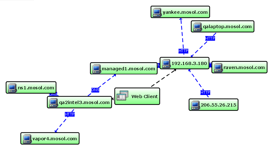
The Organic layout renders the layout based mainly on structures and relationships. Figure 6-5 is an example of a relationship layout rendered using the Organic layout type:
Figure 6-5 Organic Layout
6.6.2 Using a Different Layout Style in the Relationship browser
-
Do one of the following to open the Edit Element Layout Properties dialog box:
-
In the sidebar, click
 Edit Element Layout Properties.
-
In the Control Panel, click the Edit element layout link.
-
-
In the Edit Element Layout Properties dialog box, select a layout type in the sidebar (, , , and so on).
-
If necessary, modify the settings for the selected layout on the right side of the dialog box.
These settings vary by layout type.
For information on selecting the appropriate link, see Using Layout Rendering Features.
-
Click .
The diagram updates to use the selected layout style.
6.6.3 Saving the Current Layout as an Element Preset
Layout style changes display for the current session only. Save them explicitly for future use.
To save the current layout as an element preset:
-
To save the current view as an element preset for future use, right-click the layout background, then select .
-
To select and display the saved element preset, do one of the following in the Relationship browser:
-
In the sidebar, click
 Layout Preset, then select from the drop-down list.
-
In the Control Panel, click the current Layout selection, then select from the drop-down list.
The diagram updates using the element preset.
-