8.1 Geographical View Example
Businesses whose internal resources and services span multiple geographic areas find it useful to analyze performance and target troubleshooting methods by location. For example, mergers and other types of vendor or partner relationships create interrelated business processes, such as supply chain or post-sales support. Businesses that deliver products and services across geographic areas of varying size find it useful to view service delivery levels, outages, and other problems by location. This view can help prioritize problem resolution, organize delivery or service routes, and site visits, and identify and proactively protect at‑risk areas from technology outages.
Use the Layout view to create a high-level view of the status of services and availability of resources by geographic area, without having to change existing element hierarchies or create new ones. It is easy to add a map to the Layout view, then organize relevant elements on the map.
Rather than sort through events based only on criticality or date, your staff can pinpoint “hot spots” that experience critical technology outages frequently, resulting in substandard delivery of services to customers. This helps in selecting sites for redeploying or purchasing new resources. It also keeps the IT staff focused on maintaining service availability to troubled regions, rather than just responding to alarm after alarm.
Understanding how resources impact service by location also helps IT staff alert the business to potential service disruptions. For instance, if IT cannot avoid problems with routers in the Boston area, the staff can tell business managers which customers might experience service disruptions. Together, the business and IT staff can take proactive steps to mitigate or even avoid trouble in the first place, as well as to accurately assist impacted customers.
Some business-critical applications rely on an IT infrastructure spread across multiple continents. The sheer scope of these resources makes finding the root cause of availability problems a difficult process. However, you can create Layout drawings that identify the state of applications and which particular technology components are impacting that state — all in real time. The team can quickly identify a business issue’s source and location, as well as prioritize its support workload. For example, retail bank executives want to know the state of their business in real time, such as the state of ATM operations and telephone service in different regions and branches.
Layout views can show the state of key services by city, region or country. The views have the power to drill down from, for instance, regional ATM operations to the ATMs in a specific bank. Bank executives can hold IT accountable for their services. They have immediate information on the services that drive profits and customer satisfaction. If an outage is unavoidable on the technical side, the business can take action to mitigate the impact, such as by making alternate arrangements for customers and branches.
Assume a wireless company has recently completed a merger with a smaller company. IT managers must eliminate redundant hardware and software. The challenge is realizing cost-savings while guaranteeing the reliability of critical business services, such as point-of-sale resources and credit checking.
By integrating and interpreting data from across the provider’s infrastructure and viewing it by geographic region, IT staff can identify technology issues to focus on first. For instance, IT executives can measure the results of a resource consolidation on service availability in key cities.
Another important goal after a merger is consolidating the large number of servers the company relied on. Managers can use Layout views to see high-level information, such as whether a key company application is available in certain regions. It’s a way for IT to communicate value, as well to keep management aware of their ability to do business. Operations Center integrates data from the manufacturer’s existing management tools. With this information, Operations Center continuously determines — in real time and over time — how IT resources are impacting overall services, services in a particular region, or key technology groupings in various data centers. The staff becomes focused on responding and even preventing service problems — not just reacting to alarms.
The company has organized its Operations Center business views by key applications, such as credit checking, point-of-sale data collection, and customer problem reports. These are the top-level elements in Operations Center. Within each application, server availability and performance data are rolled up into major sales markets, such as Boston, New York, Philadelphia, and Washington, DC.
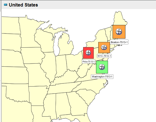
Now assume the IT manager wants to view availability status for each application by city. The completed Layout view drawing in Figure 8-1 shows the current credit checking system availability in Boston, New York, Philadelphia, and Washington, DC. Red corresponds to CRITICAL status, orange corresponds to MAJOR status, and so on. CRITICAL cities require more detailed inspection, because it is likely multiple servers are down and the credit checking system might not be functioning in the affected sales centers.
Figure 8-1 illustrates that the cities are linked to existing elements and their current condition. The red CRITICAL squares indicates problems exist with the credit checking system in NYC and Washington DC.
Figure 8-1 Map Example
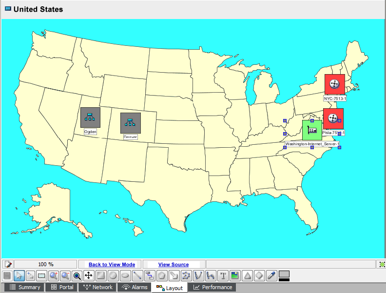
In this example, each city is represented by a small circle whose fill color matches the city availability condition and by text displaying the city name. Each city is bound to an element in the hierarchy.
Creating this type of view consists of:
-
Adding specific elements to the drawing
-
Adding a map image to the Layout background
-
Adding a title, change the background color
-
Changing the background color
-
Saving the drawing
To create conditions across a map:
-
In the pane, select an element.
The Layout drawing will be associated with this element. In this example, we created a new element named .
-
In the bottom of the Layout view, click . The drawing clears and switches to Edit mode.
-
Place the elements from the hierarchy that will be used in this drawing.
The display format used for each element is called a node style.
Operations Center ships with many different node styles. You can simply select one, then drag and drop it on a drawing.
Select a node style to format the cities displayed in the drawing.
-
In the pane, expand and locate the elements that should be surfaced in this drawing.
In this example, we expand > .
You can click the plus (+) and minus (–) symbols to expand and collapse element hierarchies. However, do not click an element name in the pane or the Layout view shifts to that element and away from the element.
-
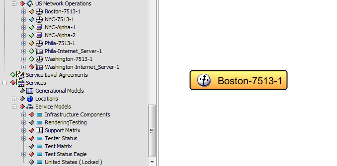
From the pane, drag and drop Boston to the Layout view.
-
From the pop‑up menu, select .
The default node style displays to represent Boston:
-
Expand > > .
-
Locate the node style you want use (ClassicSmall is used in this example) and drag it to Boston.
-
From the menu, select .
Boston updates to use the new node style.
-
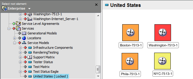
Drag the remaining cities from the pane to the Layout view.
Select for all of them.
Notice that the circle fill colors automatically change to match the city elements’ current conditions.
The fill colors for the squares are bound to the element conditions:
-
-
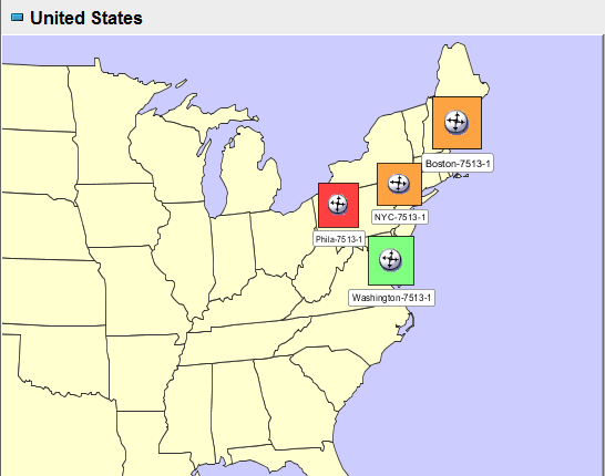
Add a background map and arrange geographical locations:
The final steps to complete the drawing consist of
A number of maps ship with Operations Center. You can also import maps. In this example. we are adding a background map of the United States and arranging the cities in the correct geographic locations.
-
Click the tab.
-
From the drop-down list, select .
-
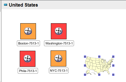
Drag and drop the US Map to the view pane:
-
Right-click the map, then select > .
-
Resize the map graphic by dragging its endpoints until it is approximately the same size as the one shown in the following:
-
Click and drag the cities to the appropriate geographic location on the map.
-
-
Add text to complete the drawing. We are adding a title and background color, before saving the drawing.
-
Create a title for the drawing by clicking
 () on the drawing tools toolbar.
-
Enter Availability by City.
-
Change the text size, font, or color using the property panes.
-
Drag the title to the appropriate location.
-
Right-click the Layout view, then select .
-
Select a color from the palette, then click .
The background color updates.
-
-
Click > .
The finished drawing:
Notice that placing the mouse over any drawing object that is linked to an element displays a summary of the element condition. In this example, place the mouse over the city name or symbol.