A.1 Element Rendering Look Up Strategy
In the context of the Operations Center Layout view, element rendering is performed by locating the selected node style or graphic representation for a specific element in a specific drawing.
This property can be set in many places. A default lookup strategy determines which node style or graphic rendering to use for an element in a drawing. Referring to Figure A-1, the lookup works from top to bottom:
Figure A-1 Nodestyle Flowchart
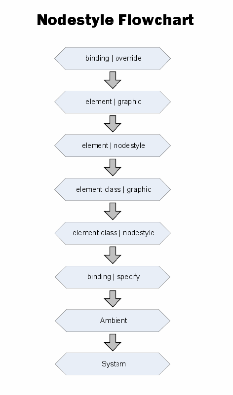
The lookup strategy is performed in the following order:
-
binding | override (* DRAWING SPECIFIC)
Use this setting to override all other node styles and graphics in a drawing and assign a specific node style for a specific element.
-
element | graphic
An element in a drawing has a custom graphic defined for this instance of the element. This graphic is specified in the element’s Element Graphic drawing channel. This graphic might have been created by a user in v4.0, or it could result from a conversion from v3.5.x for an element that contained a custom graphic.
-
element | node style
An element in a drawing has a custom node style defined for this instance of the element. This graphic is specified in the Element Node Style drawing channel. This channel is merely a reference to a custom node style listed under > > .
-
element class | graphic
An element in a drawing has a class definition with a custom graphic defined. This graphic is specified in the Element Graphic drawing channel for this instance of the class definition, which appears in the branch of the hierarchy.
IMPORTANT:There is currently an open issue with these two element class options. Only Org type elements support these settings. This is a constraint put in place by the Metamodel implementation.
-
element class | node style
An element in a drawing has class definition with a custom node style defined. This is specified in the Element Node Style drawing channel for this instance of the class definition, which appears in the branch of the hierarchy.
-
binding | specify ( * DRAWING SPECIFIC)
An element was added to a drawing using the option. The user chose to set a node style for the all elements generated by this layout option.
HINT:This setting can be overridden by the higher priority settings that are found for each element in the binding.
-
Ambient ( * DRAWING SPECIFIC)
The Ambient node style changes all elements that currently use the system default node style. It is a way to quickly change multiple nodes at once. Drag and drop a node style to the drawing background.
-
System
There is no node style set on a drawing and no node style or graphic found for the target element by searching the list above.
The subsequent sections provide examples of how the element rendering priorities work. Start by creating custom classes and apply them to new elements, then create a corresponding portal. You can create several node styles and apply them.