3.5 Configuration Tips for the L4 Switch
When you use an L4 switch to cluster Identity Servers, Access Gateways, or both, you need to configure it and the DNS server for each cluster. You need to configure the DNS server to resolve the base URL of the Identity Server configuration to the Identity Server VIP on the L4 switch. You need to configure the DNS server to resolve the published DNS names of the Access Gateway to the Access Gateway VIPs on the L4 switch.
In addition to this basic setup, consider the following:
3.5.1 Sticky Bit
Each L4 switch has a slightly different method and terminology for the sticky bit or persistence bind. This bit allows a client that has established a session to be directed to the same Identity Server or Access Gateway for all requests sent during the session. This minimizes the need to forward session information between Access Gateways or between Identity Servers and thus maximizes performance.
3.5.2 Network Configuration Requirements
When you set up the L4 switch, be aware of the following configuration requirements that are required to route all Access Manager traffic through the L4 switch:
Switches: When you install an L4 switch, you can plug the machines directly into the L4 switch or plug them into an inner switch that is plugged into the L4 switch. When you use inner switches with an L4 switch, you must use at least two inner switches, one for the Identity Servers and one for the Access Gateways. An Identity Server and an Access Gateway cannot share the same inner switch. Such a configuration causes communication problems because the Access Gateway and the Identity Server try to establish direct communication with each other rather than routing all traffic through the L4 switch.
Network Routing Requirements: You need to analyze your routing configuration. The Identity Servers and the Access Gateways must be connected to separate ports in the L4 switch. If there is a connection in your network that allows an Identity Server or an Access Gateway to communicate directly with a client without going through the L4 switch, the Access Gateway and the Identity Server try to establish direct communication with the client because networking protocols are configured to select the most direct route. Such a configuration causes communication problems because all traffic must be routed through the L4 switch. Figure 3-3 illustrates this problem.
Figure 3-3 Network Configuration with a Potential Communication Problem
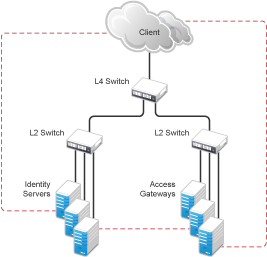
If your network allows for this type of communication, you need to block the communication channels illustrated with the dotted lines.
Figure 3-3 shows each cluster type with its own L2 switch. An Access Gateway cluster and an Identity Server cluster cannot share the same L2 switch because they can see the MAC address for each other. Networking protocols are configured to use the most direct route for the communication, and the MAC address is more direct than going up to the L4 switch and back down. Such a configuration causes communication problems because all traffic between the clusters needs to be routed through the L4 switch. Using a separate L2 switch for each cluster type prevents them from gaining access to the MAC address and forces communication to take place through the L4 switch.
3.5.3 Health Checks
L4 switches use health checks to determine which cluster members are ready to receive requests and which cluster members are unhealthy and should not receive requests. You need to configure the L4 switch to monitor the heartbeat URL of the Identity Servers and Access Gateways, so that the L4 switch can use this information to accurately update the health status of each cluster member.
The procedure is slightly different for Identity Servers and Access Gateways:
Health Checks for an Identity Server
The Administration Console uses the heartbeat URL to display the health status of the Identity Servers. The Identity Server heartbeat is the DNS name of the Identity Server plus the following path:
/nidp/app/heartbeat
L4 switches require you to use IP address rather than the DNS name. If the IP address of the Identity Server is 10.10.16.50, and you have configured the Identity Server for HTTPS, the heartbeat has the following URL:
https://10.10.16.50:8443/nidp/app/heartbeat
You need to configure the L4 switch to use this heartbeat to perform a health check. If you have configured SSL on the Identity Servers and your L4 switch has the ability to do an SSL L7 health check, you can use HTTPS. The SSL L7 health check returns a value of 200 OK, indicating that everything is healthy; any other status code indicates an unhealthy state.
For a Foundry switch, the L7 health check script string should look similar to the following when the hostname is nidp1 and the IP address is 10.10.16.50:
healthck nidp1ssl tcp
  dest-ip 10.10.16.50
  port ssl
  protocol ssl
  protocol ssl url "GET /nipd/app/heartbeat HTTP/1.1\r\nHost: st160.lab.tst"
  protocol ssl status-code 200 200
  l7-check
If your switch does not support an SSL L7 health check, the HTTPS URL returns an error, usually a 404 error. Because the Identity Server heartbeat URL listens on both HTTPS and HTTP, you can use an HTTP URL for switches that do not support the SSL L7 health check. For example:
http://10.10.16.50:8080/nidp/app/heartbeat
An Alteon switch does not support the L7 health check, so the string for the health check should look similar to the following:
open 8080,tcp
send GET /nidp/app/heartbeat HTTP/1.1\r\nHOST:heartbeat.lab.tst \r\n\r\n
expect HTTP/1.1 200
close
Health Checks for the Access Gateway
External communication to the Access Gateway is typically configured to use HTTPS. In an HTTPS configuration, an L4 switch performs health checks of the Access Gateways with the published DNS name of the Access Gateway plus the following path:
/nesp/app/heartbeat
L4 switches require you to use IP address rather than the DNS name. If the IP address of the Access Gateway is 10.10.16.172, and you have configured the Access Gateway for HTTPS, the heartbeat has the following URL:
https://10.10.16.172:443/nesp/app/heartbeat
For an L4 switch to support an HTTPS query for the health of the Access Gateway, the switch must support an L7 health check. For a Foundry switch, the L7 health check script string should look similar to the following when the hostname is ag1 and the IP address is 10.10.172.
healthck ag1ssl tcp
  dest-ip 10.10.16.172
  port ssl
  protocol ssl
  protocol ssl url "GET /nesp/app/heartbeat HTTP/1.1\r\nHost: st160.lab.tst"
  protocol ssl status-code 200 200
  l7-check
If your L4 switch does not support an SSL L7 health check, the HTTPS health check URL returns an error, usually a 404 error. To solve this problem, you can create a specialized reverse proxy that opens a non-SSL port for the heartbeat URL. The following instructions configure this reverse proxy to use port 81, because port 80 on the specified IP address is reserved for redirects to the SSL port.
To create a reverse proxy for the health check:
-
In the Administration Console, click > > > .
-
To create an additional reverse proxy service (such as heartbeat), click , then specify a name.
-
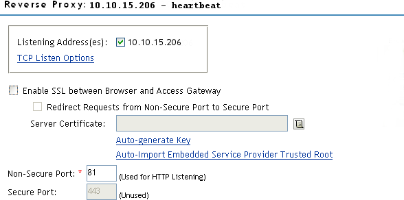
Change the to 81.
You configure the Access Gateway to listen on the same IP address as the service using port 443. For non-SSL, port 81 is recommended. Do not use port 80.
For proper heartbeat information when there are multiple IP addresses configured in your Access Gateway, ensure that you configure the reverse proxy service created for the heartbeat URL to listen in the same IP address as the authenticating reverse proxy service.
-
Click to create the proxy service.
-
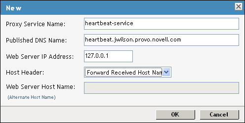
Configure the following fields:
Proxy Service Name: Specify a name that identifies the purpose of this proxy service.
Published DNS Name: Specify a second DNS name that resolves to the VIP of the Access Gateways on the L4 switch. For example, if the DNS name is jwilson.provo.novell.com for the Access Gateways, you could use heartbeat.jwilson.provo.novell.com for the second name.
Web Server IP Address: Specify the internal address:127.0.0.1.
Host Header: Select . This field is not used.
-
Click .
-
On the Reverse Proxy page, click the new proxy service, then click .
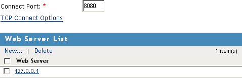
-
Change the value on the Web Servers page to 8080.
The service provider (ESP) in the Access Gateway that provides the heartbeat service listens on 127.0.0.1:8080.
-
Click .
-
Click , then specify a name.
-
In the URL Path List, click /*, and modify the path to contain the following value:
/nesp/app/heartbeat
This is the path to the heartbeat application.
-
Click twice. Your protected resource for the heartbeat application should look similar to the example below.
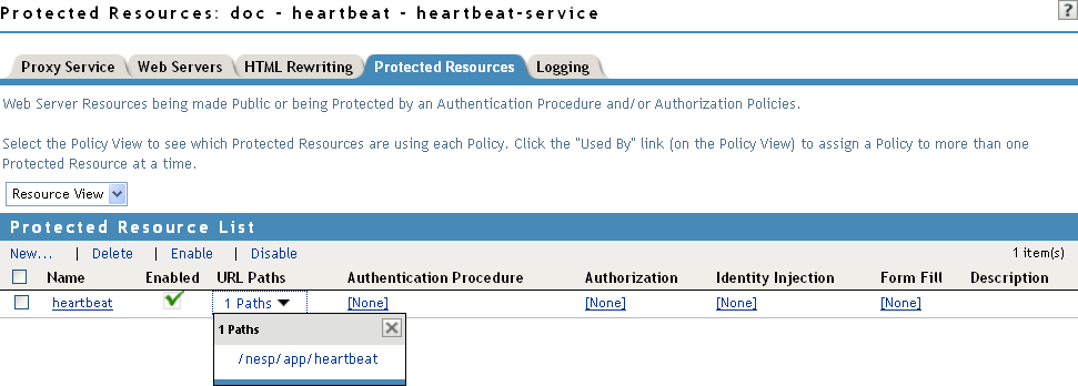
The heartbeat of this Access Gateway is available from the following URL (See Step 4.):
http://heartbeat.jwilson.provo.novell.com:81/nesp/app/heartbeat
If the protected resource is configured with a path of / or /*, the solution works but it can be vulnerable to attacks because the configuration opens the ESP over a non-SSL port. Restricting the resource to /nesp/app/heartbeat automatically denies access to the ESP except for the heartbeat.
-
Click and apply the changes to the configuration.
-
Add a line similar to the health check script:
For a Foundry switch, your string should look similar to the following if the hostname is ag1 and the IP address is 10.10.16.172:
healthck ag1 tcp
  dest-ip 10.10.16.172
  port http
  protocol http
  protocol http url "GET /nesp/app/heartbeat HTTP/1.1\r\nHost:st160.lab.tst"
  protocol http status-code 200 200
  l7-check
For an Alteon switch, your string should look similar to the following if the hostname is ag1 and the IP address is 10.10.16.172:
open 81,tcp
send GET /nesp/app/heartbeat HTTP/1.1\r\nHOST:heartbeat.lab. tst\r\n\r\n
expect HTTP/1.1 200
close
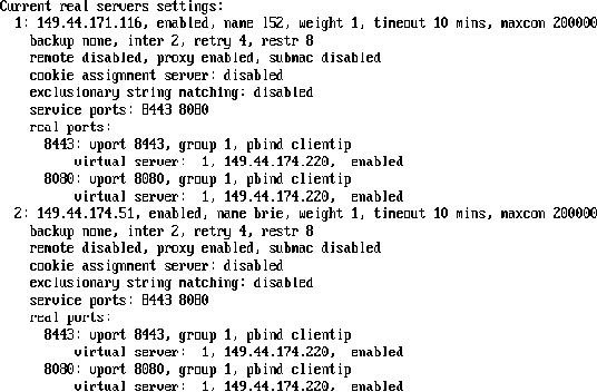
3.5.4 Real Server Settings Example
After setting up the health checks, you need to configure the real server settings. The following is an example from a Foundry switch.
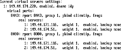
3.5.5 Virtual Server Settings Example
After setting up the real server settings, you need to configure the virtual server settings. The following is an example from a Foundry switch.