A.8 Applying a Graphic to a Class
A.8.1 Changing the Class Node Style to a Custom Graphic
The following section of the example changes the node style of a class to a custom graphic and tests the element class | graphic switch.
To change a class node style to a custom graphic:
-
In the pane, under > , select the custom class.
-
On the console toolbar, switch to the drawing channel.
-
Add the following drawing elements to the drawing:
-
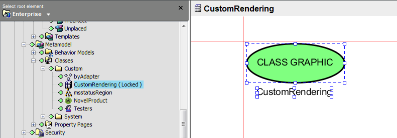
Draw an ellipse in the same location as the illustration below.
It might be necessary to pan the drawing to see the red axes, because they initially display in the upper left-hand corner. Notice that the origin of the ellipse is relative to the red axes that represent the (0,0) coordinate origin of the drawing.
-
Bind the ellipse’s fill color to element condition. The ellipse’s fill changes to green.
-
Add a label named CLASS GRAPHIC inside the ellipse.
-
Add a label beneath the ellipse and bind that label to the option.
-
-
Save the drawing.
-
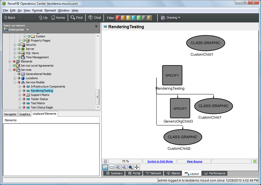
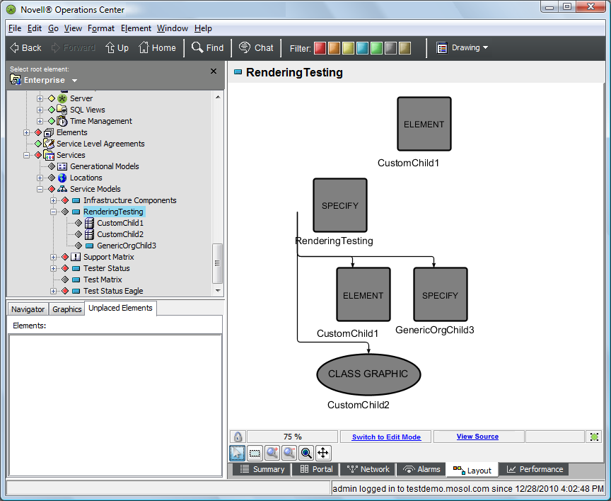
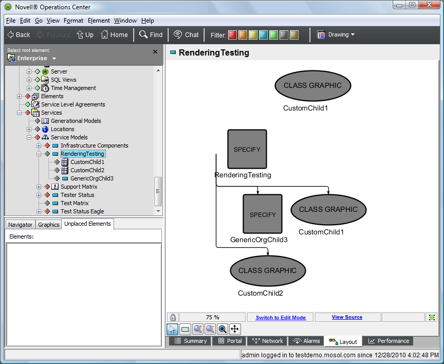
Return to the element and verify that all element instances of the custom class now use the custom drawing graphic.
This feature allows the user to control custom graphics from the class level.
The drawing should resemble the following:
-
Refresh the Operations Center dashboard page and verify the same view displays.
A.8.2 Applying a Node Style at the Element Instance Level
The following example applies a node style at the element instance level and tests the element | node style switch.
To apply a node style at the element instance level:
-
In the pane, select the element > .
-
Switch to the Element Node Style drawing channel.
-
In the pane, under > > , drag and drop the node style to the Layout view.
This should set the node style to for the element class.
-
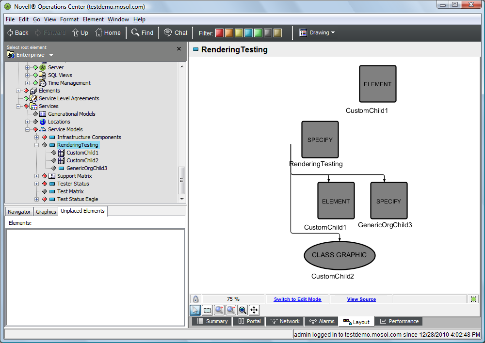
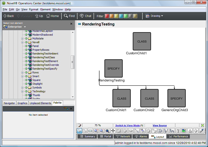
Return to the view and verify that all copies of the element now use the node style.
This allows you to control node styles from the element instance level. In every drawing where this element appears, this graphic is used, unless it is overridden by a higher priority rendering.
The drawing should resemble the following:
-
Refresh the Operations Center dashboard page and verify the same view displays.
A.8.3 Applying a Graphic at the Element Instance Level
The following section of the example applies a graphic at the element instance level and test the element | graphic switch.
To apply a graphic at the element instance level:
-
In the pane, select the > element.
-
Switch to the drawing channel.
-
Edit the drawing using the following steps:
-
Draw a rectangle in the same location as the following:
It might be necessary to pan the drawing to see the red axes as they initially display in the upper left-hand corner. Notice how the origin of the rectangle is relative to the red axes that represent the (0,0) coordinate origin of the drawing.
-
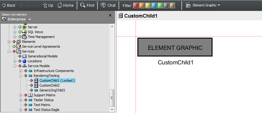
Bind the rectangle’s fill color to element condition.
-
Add a label named ELEMENT GRAPHIC inside the rectangle.
-
Add a label beneath the rectangle and bind that label to the option.
-
-
Save the drawing.
-
Return to the view.
-
Verify that all copies of the element now use the custom graphic.
This allows you to control graphics from the element instance level. In every drawing where this element appears, this graphic is used, unless it is overridden by a higher priority rendering.
The drawing should resemble the following:

-
Refresh the Operations Center dashboard and verify the same view displays.
A.8.4 Overriding a Single Element Node Style
The following section of the example overrides the node style for a single element and tests the bind | override switch.
To override the node style for a single element:
-
In the pane, select the element.
-
On console toolbar, verify the channel is selected.
-
In the pane, under > > , drag and drop the node style to the element in the Layout view.
The element is part of the nested tree layout.
-
Select from the pop‑up menu.
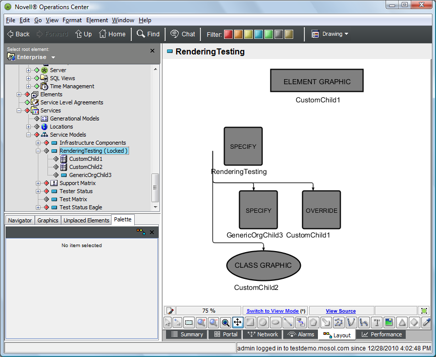
The node style changes to for only one copy of . This override setting only applies to the binding that caused the element to display in the drawing. The other copy of still uses the custom element graphic set in the previous section.
The drawing should resemble the following:
-
Save the drawing.
-
Refresh the Operations Center dashboard page and verify the same view displays.
-
While still viewing the element, drag and drop the node style to the orphaned element in the layout that is not part of the nested tree layout.
-
Select from the pop‑up menu.
This should set the node style to for only this copy of the element in this drawing.
The drawing should resemble the following:
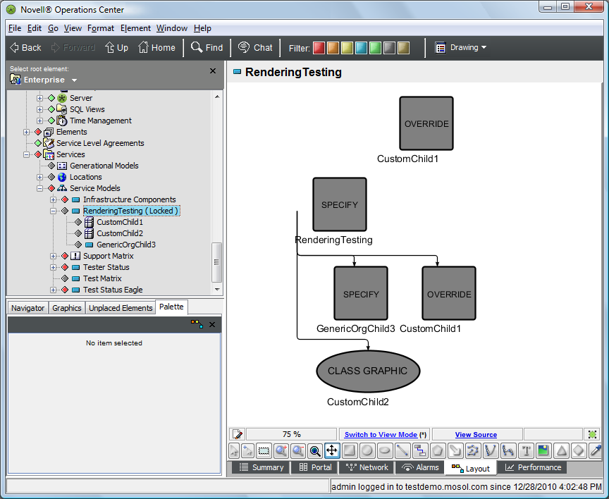
Now, each copy of the element has its own override rendering.
-
Save the drawing.
-
Refresh the associated portal and verify the same view displays.
A.8.5 Clearing Previously Set Node Styles and Graphics
The following sections cover how to clear the various types of node styles and graphic switches.
NOTE:There is currently no option in the Operations Center console for clearing the Ambient setting or the binding|specify setting. These settings can be cleared by directly editing the SVG source, which is explained in Section C.0, Editing the Source SVG Code.
Clearing the Bind | Override Switch
To clear the bind | override switch:
-
In the pane, select the element.
-
On the console toolbar, verify the channel is selected.
-
Switch to Edit mode.
-
Right-click the orphaned element in the layout that is not part of the nested tree layout.
-
Select from the menu, then click to remove the override.
-
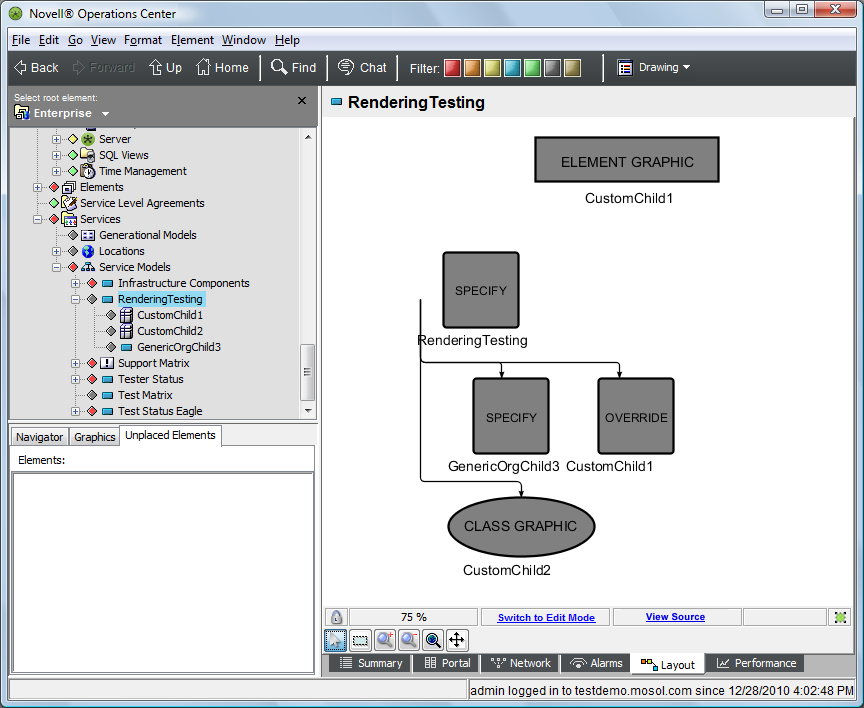
Verify that the override is removed from only this copy of .
The drawing should resemble the following:
There might be a short delay before the old rendering is cleared from the graphics cache.
-
Save the drawing.
-
Refresh the Operations Center dashboard page and verify the same view displays.
-
Switch to Edit mode and right-click the element that is part of the nested tree layout.
-
Select from the menu, then click to remove the override.
-
Verify that the override is removed from only this copy of CustomChild1.
There might be a short delay before the old rendering has been cleared from the graphics cache.
The drawing should resemble the following:
-
Save the drawing.
-
Refresh the Operations Center dashboard page and verify the same view displays.
Clearing the Element | Graphic Switch
To clear the element | graphic switch:
-
In the pane, select the element.
-
On the console toolbar, switch to the drawing channel.
-
Right-click the background, then select .
-
Click to accept.
-
Verify that the Element Graphic drawing channel is cleared.
-
Return to the view.
All copies of the element have reverted to the element instance node style.
There could be a short delay before the old rendering is cleared from the graphics cache.
The resulting drawing should resemble the following:
-
Refresh the Operations Center dashboard and verify the same view displays.
Clearing the Element | Node Style Switch
To clear the element | node style switch:
-
In the pane, select the element.
-
On the console toolbar, switch to the drawing channel.
-
Click in the upper right-hand corner of the view.
-
Verify the node style clears and the text in the center changes to none.
-
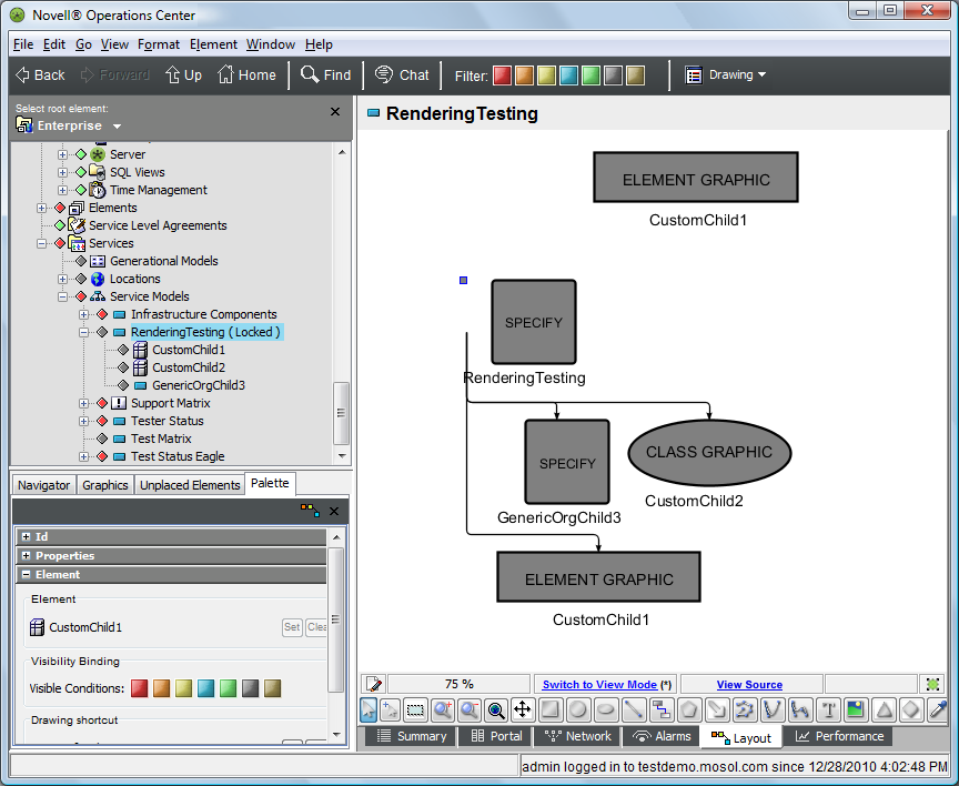
Return to the view and verify all copies of the element have reverted to their class definition’s custom graphic (defined for the custom class).
There could be a short delay before the old rendering is cleared from the graphics cache.
The resulting drawing should resemble the following:
-
Refresh the associated portal and verify the same view displays.
Clearing the Element Class | Graphic Switch
To clear the element class | graphic switch:
-
In the pane, expand > > > the custom class.
-
On the console toolbar, switch to the drawing channel.
-
Right-click the drawing, then select
-
Click to accept.
-
Verify that the Element Graphic drawing channel is cleared.
-
Return to the Layout view and verify that all copies of the element have reverted to their class definition’s node style.
There can be a short delay before the old rendering is cleared from the graphics cache.
The resulting drawing is shown in the following:
-
Refresh the associated portal and verify the same view displays.
Clearing the Element Class | Node Style Switch
To clear the element class | node style switch:
-
In the pane, select the class.
-
On the console toolbar, switch to the drawing channel.
-
Click in the upper right-hand corner of the view.
-
Verify the node style clears and the text in the center changes to none.
-
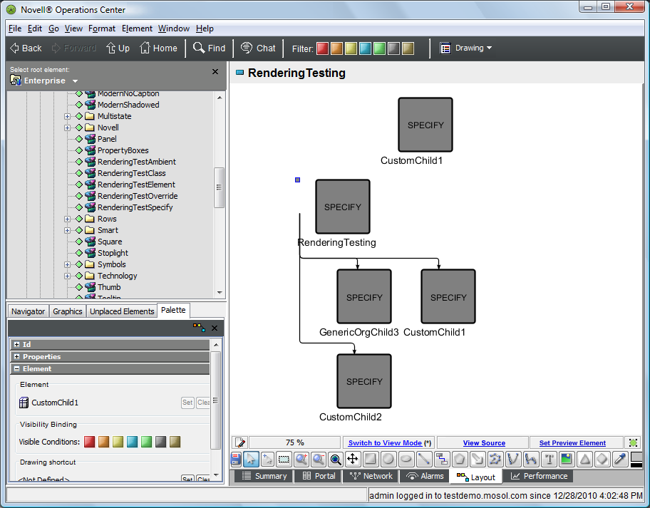
Return to the view and verify that all copies of the element have reverted to the SPECIFY node style.
At this point the Ambient node style is using the node style and the binding node style is also set to .
There could be a short delay before the old rendering is cleared from the graphics cache.
The resulting drawing should resemble the following:
-
Refresh the associated portal and verify the same view displays.