4.4 Exploring Hierarchies Using the Network View
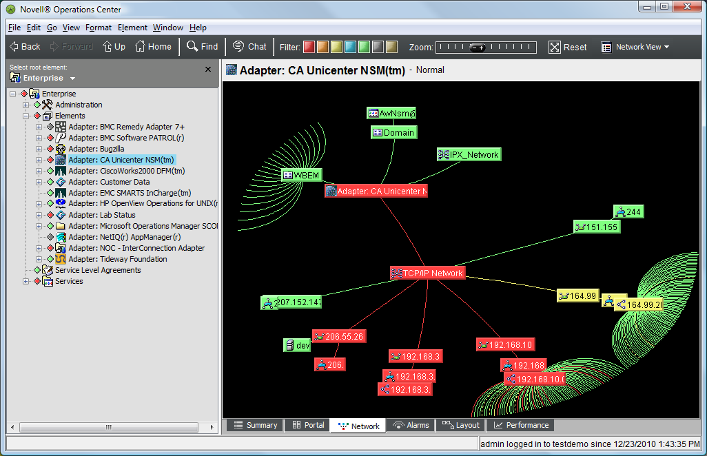
The view provides a dynamic graphical interface that enables moving across the entire enterprise, managing applications, servers, and network components.
The view displays relationships among system components within a large infrastructure. The view displays the selected element at the center, with spokes connecting to first-level child elements. Additional lines connect the first level elements to their children. The line colors identify the conditions of the child elements.
The view might not be available to users who are not in the administrators group if it was disabled. For more information, see Disabling the Network and Layout Views
in the Operations Center 5.0 Server Configuration Guide.
The element selected in the pane determines which elements display in the view and whether the entire network displays or only a portion of it. The elements displayed in the view also depend on user access privileges.
There are various ways to move around the view. Use menu options and toolbar buttons to view different levels of detail.
Initially, the element selected in the pane displays in the center of the view:
Figure 4-7 Network View
The following sections describe how to use the various features of the view:
4.4.1 Changing the Viewing Level of the Elements
You can view elements at a higher or lower level than the selected element. Table 4-2 provides some examples.
Table 4-2 Network View Actions
|
Action |
Result |
|---|---|
|
On the toolbar, click the button. |
The selected element’s parent moves to the center of the view. |
|
On the toolbar, click the button. |
The top-level view displays. The element displays at the center of the view with lines connecting to the first level elements. |
|
Click and drag the network to center a different section on the screen. |
A new section displays at the center of the view. |
|
Click an element once. |
The element moves to the center of the view. The network diagram shifts accordingly, bringing into view the elements connected to the selected element. |
|
Double-click an element. |
The selected element moves to the center of the network and its child elements display. |
|
Click anyplace on the network background in the direction in which the network should move. For example, to scroll to the right, click anyplace in the right side of the network background. |
The view shifts in the selected direction. It brings into view elements that were not previously visible. |
4.4.2 Selecting the Magnification Level
Use the slider to increase or decrease the level of detail displayed in the view:
Figure 4-8 Zoom Slider
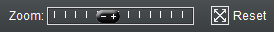
Table 4-3 provides some examples of how to use the slider.
Table 4-3 Zoom Slider Actions
|
Action |
Result |
|---|---|
|
Move the slider to the right. |
Magnifies (zooms in) the view. Fewer elements display, and the lines connecting them enlarge. |
|
Move the slider to the left. |
Shrinks (zooms out) the view. More elements display and the lines connecting them shrink. |
|
On the toolbar, click the button. |
Returns to the default magnification level. The default view displays. |
4.4.3 Shifting the View to Follow Condition Changes
You can enable the menu option to immediately move any elements that experience condition changes to the center of the view:
Automatically Shifting the View to Follow Condition Changes
To shift the view to follow element condition changes:
-
Click , then select .
Enable the feature to cause elements to blink when their conditions change. However, the view does not move these elements to the center of the screen.
Causing Elements to Blink When Condition Changes Occur
To blink elements when element condition changes:
-
Click , then select .
In the view, elements whose condition change blink.
4.4.4 Changing the Network Orientation
Use the menu options in the console’s menu bar to change the orientation of elements displayed in the view.
To change the orientation of displayed elements:
-
From the menu, click , then select one of the following:
Radial: The selected element displays in the center of the screen, with lines connecting it to other elements in a circle.
Top-Down, Bottom‑Up: The selected element displays at the top or bottom of a vertical hierarchy, with lines connecting it to other elements.
Left-to-Right, Right-to-Left: The selected element displays in the far left or right of the screen in a horizontal hierarchy, with lines connecting it to other elements.