5.6 Using the Element Binding Options
A drawing component, such as a shape or line, can be bound to an element in the pane. For example, bind the element condition color to the shape fill color or line fill color. A red square representing a network helps quickly identify a CRITICAL network problem in a drawing.
Text added to a drawing can be bound to an element name, DName, or attribute.
Typically, the bind is performed by creating the shape, then dragging and dropping an element to the shape. By default, the element’s condition is bound to the shape’s fill color.
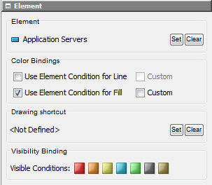
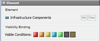
When element binding is used, the pane displays the name of the Operations Center element to which the drawing component is bound. The pane functions are:
-
Bind the drawing component to a different Operations Center element or remove binding altogether from the drawing component.
-
Determine whether the element condition color should fill and/or shade the lines of the drawing component.
-
For text elements, determine whether to bind the element name, DName, or attribute value.
Keep in mind that the drawing itself remains bound to the element currently selected in the hierarchy—the drawing “owner.” Initially, element binding is inherited throughout the drawing. All children inherit the drawing owner’s DName information. This inheritance is changed when you use the Bind feature described in the following subsections to bind a different element to a child in the drawing:
5.6.1 Binding to a Different Element
Binding a Drawing Component
To bind a drawing component to a different Operations Center element:
-
In the pane, click in the section:
This opens the Browse for Element dialog box.
-
Select the element, then click .
The pane updates to display the selected element in the section, and the drawing component is linked to the newly selected element.
Removing the Binding
To remove the binding from the drawing component:
-
In the section of the pane, click :
A dialog box displays asking you to confirm removing the binding.
-
Click .
The drawing component is no longer bound to the Operations Center element. However, keep in mind the drawing remains linked to the current element in the pane.
5.6.2 Binding Elements Using Condition Color
After binding an element to a drawing component, decide whether to use the element’s condition color to shade the drawing shape. Use this feature to have the drawing shape’s color change automatically whenever the element condition changes.
Using the Condition Color to Shade the Drawing Component
-
In the pane, select one or both of the following check boxes:
The drawing component colors update to match the element condition.
If an adapter shuts down and any of its element conditions are bound as fill colors to drawing shapes, these shapes change to the UNKNOWN state. No tooltips are available while the adapter is down.
-
Customizing Element Condition Colors
There could be situations when you want to define the element condition color used to shade bound drawing components. For example, if an element condition is CRITICAL, MAJOR, or MINOR, the drawing component (such as a square) should be red. If the element is in any other condition, the square should be green, as if it were in the OK state.
Customizing Condition Color
To customize the element condition color:
-
Click the check box next to :
-
Select from the drop-down list, then click the red, orange, and yellow squares next to :

If the linked element is in the CRITICAL, MAJOR, or MINOR state, the drawing component is shaded red, as though it were .
-
Select from the drop-down list.
If the linked element is in any other state, the drawing component is shaded green, as though it were .
Defining Custom Condition Color
Another application of this feature is to define a custom color for the default or set condition. For example, use a custom magenta color when the condition is MAJOR or MINOR.
To define a custom condition color:
-
Select the check box next to :

-
Select from the drop-down list.
-
Click the color block to the right to display the custom color palette:

-
Define the custom color, then select it.
-
Click the orange (MAJOR) and yellow (MINOR) squares.
If the element condition is either MAJOR or MINOR, the bound drawing component is shaded using the custom color (in this example, magenta).
-
In the drop-down list, select a condition to use when the element is in any other state except MAJOR or MINOR.
In this example, the drawing component is shaded green (OK) if it is in any state except MAJOR or MINOR:

Hiding Elements Based on Condition
The Visibility Binding feature specifies the element conditions that determine whether elements are displayed or hidden in the Layout view. By default, all conditions are displayed.
Elements can be hidden only in drawings that are in the View mode (read only).
To hide elements with one or more conditions:
-
In the section of the pane, click one or more condition buttons to hide all elements that have the conditions when the drawing is in View mode (read only).
The button appearance changes when it is hidden.
In Edit mode, all hidden elements display:
The element does not display in the drawing in Edit mode when its condition is UMANAGED or UNKNOWN.
Using the Drawing Shortcut Feature
The drawing shortcut feature enables you to double-click an element in the Layout view and go to (select) a different element in the pane. This rule provides an exception to the default drill-down behavior for an element.
To set up the Drawing Shortcut:
-
In the section of the pane, click to open the Browse for Element dialog box.
-
Navigate to the element, then click .
The selected element name displays in the section:

When the object is double-clicked in the Layout view, the Layout view drawing drills in to show the drawing, which is in a different branch of the element hierarchy, because of the defined Drawing Shortcut.
HINT:When an element is bound to a shape and you hover the mouse over the element in View mode, the status bar displays the name of the bound element as a link to the shape. However, when a drawing shortcut exists and you hover the mouse over the affected element, the status bar displays the drawing shortcut element name as the link to the shape.