A.2 Installation Procedure
This section explains the procedure to install and configure the following to set up the cluster environment. For more infomration about configuring the SLES High Availability Extension, see the SUSE Linux Enterprise High Availability Extention guide.
A.2.1 Configuring the iSCSI Server
An iSCSI target is a device that is configured as a common storage for all nodes in a cluster. It is a virtual disk that is created on the Linux server to allow remote access over an Ethernet connection by an iSCSI initiator.An iSCSI initiator is any node in the cluster that is configured to contact the target (iSCSI) for services. The iSCSI target should be always up and running so that any host acting as an initiator can contact the target. Before installing iSCSI target on the iSCSI server, ensure that the iSCSI target has sufficient space for a common storage.Install the iSCSI initiator packages on the other two nodes after installing SLES 11 SP3.
During the SLES 11 SP3 installation:
-
Create a separate partition and specify the partition path as the iSCSI shared storage partition.
-
Install the iSCSI target packages.
To configure the iSCSI server:
-
Create a block device on the target server.
-
Type the yast2 disk command in terminal.
-
Create a new Linux partition, and select Do not format.
-
Select Do not mount the partition.
-
Specify the partition size.
-
Type the yast2 iscsi-server command in terminal.
-
Click the Service tab, then select When Booting in Service Start.
-
In the Targets tab, click Add to enter the partition path (as created during the SLES installation).
-
Click Finish.
-
Run the cat /proc/net/iet/volume command in the terminal to verify if the iSCSI target is installed
A.2.2 Configuring the iSCSI initiator on all Nodes
You must configure the iSCSI initiator on all cluster nodes to connect to the iSCSI target.
To configure the iSCSI initiator:
-
Install the iSCSI initiator packages.
-
Run the yast2 iscsi-client in terminal.
-
Click the Service tab and select When Booting in Service Start.
-
Click the Connected Targets tab, and click Add to enter the IP address of the iSCSI target server.
-
Select No Authentication.
-
Click Next, then click Connect.
-
Click Toggle Start-up to change the start-up option from manual to automatic, then click Next.
-
Click Next, then click OK.
-
To check the status of the connected initiator on the target server, run the cat /proc/net/iet/session command on the target server. The list of initiators that are connected to iSCSI server are displayed.
A.2.3 Partitioning the Shared Storage
Create two shared storage partitions: one for SBD and the other for Oracle Cluster File System 2 (OCFS2).
To partition the shared storage:
-
Run the yast2 disk command in terminal.
-
In the Expert Partitioner dialog box, select the shared volume. In our example, select sdb from the Expert Partitioner dialog box.
-
Click Add, select Primary partition option, and click Next.
-
Select Custom size, and click Next. In our example, the custom size is 10 MB.
-
Under Formatting options, select Do not format partition. In our example, the File system ID is 0x83 Linux.
-
Under Mounting options, select Do not mount partition, then click Finish.
-
Click Add, then select Primary partition.
-
Click Next, then select Maximum Size, and click Next.
-
In Formatting options, select Do not format partition. In our example, specify the File system ID as 0x83 Linux.
-
In Mounting options, select Do not mount partition, then click Finish.
A.2.4 Installing the HA Extension
To install the HA extension:
-
Go to the NetIQ Downloads website.
-
In the Product or Technology menu, select SUSE Linux Enterprise HAExtension, then click Search.
NOTE:Select and install the appropriate HA extension ISO file based on your system architecture.
-
Download the ISO file on each server.
-
Open YaST Control Center dialog box, click Add-on products > Add.
-
Click Browse and select the local ISO image, then click Next.
-
In the Software selection and system tasks dialog box, select High Availability. Repeat this step on the other server.
A.2.5 Configuring the HA Cluster
Configure the unicast IP addresses for Heartbeat:
-
Configure the other interface on both the nodes with the static IP addresses, which will be used for node communication (Heartbeat). In our example, the IP addresses are 10.10.10.13 and 10.10.10.14 on Node1 and Node2, respectively.
-
Ping the two servers using their host names to test the connectivity between the two servers.
IMPORTANT:If the machines are unable to ping each other, edit the local /etc/hosts file and add the host names of the other nodes and their IP addresses. In our example, the /etc/hosts file contains the following:
-
10.10.10.13 sles11sp2-idm1
-
10.10.10.14 sles11sp2-idm2
-
-
On Node1, run the yast2 cluster command in the terminal.
-
In the Cluster - Communication Channels dialog box, specify the following details:
-
Set the Transport protocol to UDPU.
-
Specify the Bind Network Address, which is the network address of the unicast IP addresses. In our example, the bind network address is 10.10.10.0.
-
Specify the Multicast port. In our example, the Multicast port is 5405.
-
Click Add to enter the IP address for each node at the member address. In our example, the IP addresses are 10.10.10.13 and 10.10.10.14 on Node1 and Node2, respectively.
-
Select Auto generate Note ID, then click Next.
-
-
In the Cluster -Security dialog box, select the Enable Security Auth, set Threads to 1, then click Generate Auth Key File.
This creates an authentication key to allow other nodes to join your cluster. The key is stored in the /etc/corosync/authkey location. Copy this file to the other node.
-
In the Cluster - Service dialog box, select On--Start openais at booting, then click Start openais Now.
-
Select Start Management as well to allow the cluster to be managed by crm_gui. For more information, see Section A.2.2, Configuring the iSCSI initiator on all Nodes.
-
In the Sync Host panel, perform the following actions:
-
Click Add to add hostnames of the cluster nodes.
-
Click Generate Pre-Shared-Keys to synchronize the configuration file between nodes, then copy it to the other node. The key file is stored in /etc/csync2/key_hagroup.
-
In the Sync File pane, click Add Suggested Files to automatically generate a list of common files to synchronize between nodes.
-
Click Turn csync2 ON, then click Next.
-
Click Next, then click Finish.
-
-
Run the passwd hacluster command to set the hacluster user password on all nodes.
NOTE:Set the same password for hacluster user on nodes.
-
Run the following commands to copy the configuration files and authentication keys to the other node:
-
# scp /etc/csync2/csync2.cfg node2:/etc/csync2/
-
# scp /etc/csync2/key_hagroup node2:/etc/csync2/
-
# scp /etc/corosync/authkey node2:/etc/corosync/
-
# scp /etc/corosync/corosync.conf node2:/etc/corosync/
-
-
Reboot all the nodes after the configuration files are copied to Node2.
-
Run the csync2 -xv command.
-
Create the mkdir -p /share directory to mount the shared storage.
-
On Node2, do the following:
-
Run the yast2 cluster command in the terminal.
NOTE:The wizard window does not appear, because the configuration file is already copied over.
-
In the Service tab, select Check On -- Start openais at booting, then click Start openais Now.
-
In the Configure Csync2 tab, click Turn csync2 ON, then click Finish.
-
Create the mkdir -p /share directory to mount the shared storage.
The cluster should be up and running.
-
-
Run the crm_mon command in the terminal to verify the status. Following is a sample output:
============
Last updated: Fri Aug 5 16:38:36 2011
Stack: openais
Current DC: node1 - partition with quorum
Version: 1.1.2-2e096a41a5f9e184a1c1537c82c6da1093698eb5
2 Nodes configured, 2 expected votes
0 Resources configured.
============
Online: [node1 node2]
A.2.6 Configuring Global Cluster Options
A resource is a service or an application that is managed by the cluster. The cluster software stack monitors the resources to check if they are up and running. If the resources stop running for some reason, the cluster detects the failure and starts or restarts that resource on the other node to provide high availability. In our example, the global cluster options are configured on Node1.
To configure the HA resource on Node1:
-
Run the crm_gui command in the terminal.
-
Click Connection menu > Login. Log in using the IP address of either of the nodes.
-
Click the CRM Config tab, then change Default Resource Stickiness to a positive value.
This is to ensure that the resources in the cluster remain in the current location. In our example, the value is 1.
-
Change No Quorum Policy to ignore.
This ensures that the cluster services are up and running even if one of the nodes is down.
-
Click Apply.
A.2.7 Configuring the OCFS Resources
Before you create the OCFS2 volume, you must configure the following resources as services in the cluster:
-
distributed lock manager (DLM)
-
O2CB
-
STONITH resource
OCFS2 requires a DLM resource to run on all nodes in the cluster and is usually configured as a clone. In our example, OCFS resources are configured on Node1.
Configuring the DLM and O2CB Resources
To configure the DLM and O2CB resources on Node1:
-
Start shell and log in as root or equivalent.
-
Run the crm configure command in terminal.
-
Run the following command to create primitive resources for DLM and O2CB:
primitive dlm ocf:pacemaker:controld op monitor interval="60" timeout="60" primitive o2cb ocf:ocfs2:o2cb op monitor interval="60" timeout="60"
NOTE:The DLM clone resource controls the DLM service to ensure that the service is started on all nodes in the cluster. Due to the base group's internal co-location and ordering, the O2CB service is only started on nodes where a copy of the DLM service is already running.
-
Run the following command to create base group and base clone:
group base-group dlm o2cb clone base-clone base-group meta interleave="true" target-role="Started"
-
Run the show command to view the changes.
-
Run the commit command, then type Exit.
Configuring STONITH Resources
It is recommended to create a 10 MB partition at the start of the device. (In our example, the SBD partition is referred as /dev/sdb1.)
IMPORTANT:Ensure that you work on device names that do not change. You must work on a device using /dev/disk/by-id at the beginning of the device name. For example, to assign the device /dev/disk/by-id/scsi-149455400000000000000000003000000250600000f000000 as the SBD STONITH device, use sbd -d /dev/disk/by-id/scsi 149455400000000000000000003000000250600000f000000 create.
Run the ls -l command to verify the device name.
-
In a terminal, run the following command to initialize the SBD device on Node1:
sbd -d /dev/sdb1 create
-
Run the sbd -d /dev/sdb1 dump command to check that the following details that have been written to the device:
-
Header version: 2
-
Number of slots: 255
-
Sector size: 512
-
Timeout (watchdog): 5
-
Timeout (allocate): 2
-
Timeout (loop): 1
-
Timeout (msgwait): 10
-
Setting Up the Software Watchdog
In SLES HA Extension, the Watchdog support in the kernel is enabled by default. It is shipped with a number of different kernel modules that provide hardware-specific watchdog drivers. The appropriate watchdog driver for your hardware is automatically loaded during system boot.
Softdog is the most generic driver. As most watchdog driver names contain strings such as wd, wdt, and dog, run the following command to check the driver that is currently loaded:
lsmod | grep wd
Starting the SBD Daemon
To start the SBD daemon on Node1:
-
In a terminal, run the rcopenais stop command to stop OpenAIS.
-
Create the /etc/sysconfig/sbd file, then add the following:
SBD_DEVICE="/dev/sdb1"
#The next line enables the watchdog support:
SBD_OPTS="-W"
NOTE:If the SBD device is not accessible, the daemon fails to start and inhibit OpenAIS startup.
-
Run the yast2 cluster command in the terminal.
-
In the Configure Csync2 tab, click Add under the Sync File pane and specify the SBD file path as follows:
/etc/sysconfig/sbd
-
Click OK.
-
In the Sync File pane, click Add Suggested Files to automatically generate a list of common files to synchronize between nodes.
-
Run the csync2 -xv command.
-
Run the sbd -d /dev/sdb1 allocate <nodename> command to allocate the nodes. Run this command twice to allocate the node names to SDB device. In our example, the following commands are executed as follows.
sbd -d/dev/sdb1 allocate sles11sp2-idm1
sbd -d/dev/sdb1 allocate sles11sp2-idm2
-
Run the rcopenais start command to start OpenAIS.
Testing the SBD
To test the SBD on Node1:
-
Run the sbd -d /dev/sdb1 list command to dump the node slots and their current messages from the SBD device.
-
Run the sbd -d /dev/sdb1 message SLES11SP2-idm2 test command to send a test message to one of the nodes.
The node acknowledges the receipt of the message in the system logs. The following is a sample message:
Aug 29 14:10:00 SLES11SP2-idm2 sdb1: [13412]: info: Received command test from SLES11SP2-idm1 on disk /dev/sdb1
IMPORTANT:The acknowledgement confirms that the SBD is up and running on the node and indicates that the SBD is ready to receive messages.
Configuring the Fencing Resource
To complete the SBD setup, activate SBD as a STONITH/fencing mechanism in Cluster Information Base (CIB). Run the following commands in the terminal on Node1:
node1# crm configure
crm(live)configure# property stonith-enabled="true"
crm(live)configure# property stonith-timeout="60s"
crm(live)configure# primitive stonith_sbd stonith:external/sbd params sbd_device="/dev/sdb1" meta is-managed="true"
crm(live)configure# commit
crm(live)configure# quit
NOTE:The value set for stonith-timeout depends on the msgwait timeout. For example, if you set the default msgwait timeout value to 10 seconds, set the stonith-timeout value to 60 seconds.
Creating an OCFS2 Volume
Before you begin, prepare the block devices you plan to use for your OCFS2 volume. Leave the devices where you plan to use the OCFS2 volume as unallocated free space, then create and format the OCFS2 volume using the mkfs.ocfs2 utility.
To create the OCFS2 volume on Node1:
-
Open a terminal window and log in as root.
-
Run the crm_mon command to check if the cluster is online.
-
Create a OCFS2 file system on /dev/sdb2 that supports up two cluster nodes, then run the following command: mkfs.ocfs2 -N 2 /dev/sdb2
Mounting an OCFS2 Volume
To mount an OCFS2 volume on Node 1:
-
Start a shell and log in as root or equivalent.
-
Run the crm configure command.
-
Configure Pacemaker to mount the OCFS2 file system on each node in the cluster:
primitive ocfs2-1 ocf:heartbeat:Filesystem params device="/dev/sdb2" directory="/share" fstype="ocfs2" options="acl" op monitor interval="20" timeout="40"
-
With the following steps, add the file system primitive to the base group that you have configured in Configuring the DLM and O2CB Resources:
-
Specify the edit base-group.
-
In the vi editor, modify the group as follows, then save your changes:
group base-group dlm o2cb ocfs2-1 meta target-role = "Started"
NOTE:Due to the base group’s internal co-location and ordering, Pacemaker only starts the OCFS2-1 resource on nodes that have an O2CB resource already running.
-
-
Run the show command to check that you have configured all the required resources.
-
Run the commit command, then type Exit.
A.2.8 Configuring IP Resource
Run the following commands to configure the IP resource on Node1:
node1# crm configure

crm(live)configure# primitive clusterip ocf:heartbeat:IPaddr operations $id="clusterip-operations" op monitor interval="5s" timeout="60s" params ip="10.52.190.15" meta resource-stickiness="100" target-role="Started"

crm(live)configure# group eDir_group clusterip meta is-managed="true" target-role="Started"

crm(live)configure# show

crm(live)configure# commit
A.2.9 Installing and Configuring eDirectory and Identity Manager on Cluster Nodes
-
To install eDirectory on cluster nodes:
Install eDirectory a supported version of eDirectory. For step-by-step instructions to configure eDirectory on HA clusters, see “Deploying eDirectory on High Availability Clusters” in the eDirectory 8.8 Installation Guide.
IMPORTANT:Ensure that the virtual IP is configured on the Node1 before you install eDirectory on Node1.
-
Install Identity Manager on Node 1 using the Metadirectory Server option.
-
Install Identity Manager engine on Node 2 Server using the DCLUSTER_INSTALL option.
Run the ./install.bin -DCLUSTER_INSTALL="true" command in the terminal.
The installer installs the Identity Manager files are installed without any interaction with eDirectory.
A.2.10 Configuring the eDirectory Resource
Run the following commands to configure the eDirectory resource on Node 1:
          node1# crm configure


crm(live)configure# primitive eDirectory ocf:heartbeat:eDir88 operations $id="eDirectory-operations" op monitor interval="15s" enabled="true" timeout="60s" on-fail="restart" start-delay="30s" params eDir_config_file="/etc/opt/novell/eDirectory/conf/nds.conf" meta resource-stickiness="100" target-role="Started"

crm(live)configure# edit eDir_group
In the In the vi editor, modify the group, then add the text “eDirectory” after clusterip, as follows to save your changes:
group eDir_group clusterip eDirectory \

meta is-managed="true" target-role="Started"

crm(live)configure# show

crm(live)configure# commit
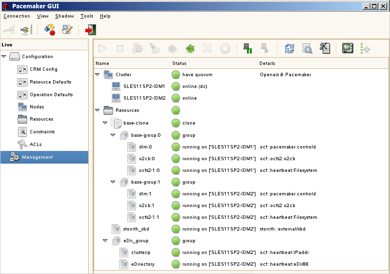
In the PaceMaker GUI main window, click Management tab, then start eDir_group if the resources are not running. The following figure shows the resources that are up and running in the cluster setup.