3.4 Configuring Networking Options and Certificates

CloudAccess contains a manual routing table, supports two Network Interface Cards (NICs), and provides a forward proxy. The forward proxy is intended only for testing purposes.

3.4.1 Configuring the Forward Proxy

The forward proxy takes requests from the internal network and forwards these requests to the Internet.

NOTE:The forward proxy is intended only for testing purposes, and is not supported in a production environment.

To configure the forward proxy:

  1. Log in with an appliance administrator account to the administration console at https://appliance_dns_name/appliance/index.html.

  2. Drag the Forward Proxy icon from the Tools palette to the Tools panel.

  3. Use the following information to configure the forward proxy:

    Forward Proxy Server: Specify the IP address and port number for your proxy server.

    Ignore List: Specify any IP addresses with the associated DNS names that you want the forward proxy to ignore. For example, 127.0.0.0|localhost. Wildcard entries are not supported in this field.

  4. Click OK to save your changes. Note that clicking OK causes the services to restart and you must log in to the appliance again.

3.4.2 Configuring the Second Network Interface

CloudAccess supports two Network Interface Cards (NICs) for each node in the cluster. You can configure one NIC for the administrative network and a second NIC for the public network. Whether the nodes in a cluster each have one or two NICs configured, the cluster itself has only two DNS names: one for the Admin NICs and one for the Public NICs.

IMPORTANT:If you configure two NICs on one appliance, you must configure all other nodes in the cluster with two NICs.

To configure the second NIC on a node:

  1. Log in with an appliance administrator account to the administration console at https://appliance_dns_name/appliance/index.html.

  2. Click a node icon, then click Configure.

  3. Click the Public Interface tab.

  4. Select Enable Separate Public Interface.

  5. Configure the network settings for your public network and click OK.

  6. (Conditional) If this is the first node in the cluster with a Public NIC, type the DNS name for the public network. Modify the keypairs for SSL and SAML as needed and click OK.

  7. Click Apply to save the changes.

  8. Click Close.

  9. Repeat Step 2 through Step 8 for each node in the cluster.

3.4.3 A Sample Network Configuration

The following graphic depicts a possible network configuration using CloudAccess with both NICs enabled on each node.

Figure 3-1 A Sample Network Diagram

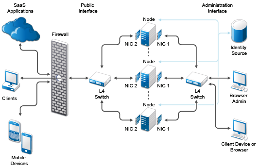
The network diagram shows that each node has both NICs enabled. The first NIC is the administration interface for the node and the second NIC is the public interface of the node. All of the administration and corporate information stays on the administration interface side of the network. All user requests and application requests communicate only on the public interface. This configuration provides a layer of security for your corporate information.

3.4.4 Configuring the Routing Table

CloudAccess provides a routing table for your use if your network has static routes. The routing table allows you to define the next hop in your network for the node in the cluster to reach the appropriate destination.

To configure the routing table for each node:

  1. Log in with an appliance administrator account to the administration console at https://appliance_dns_name/appliance/index.html.

  2. Click the node icon, then select Configure.

  3. Click the Routing tab.

  4. Specify the appropriate Reverse Path Filter setting.

    Reverse path filtering is used to prevent packets that arrived through one interface from leaving through a different interface. If you are in doubt, leave the default setting of Strict mode, because it prevents users from spoofing IP addresses from local subnets and reduces the likelihood of distributed denial-of-service (DDoS) attacks.

  5. Click the plus sign (+) to add a route.

  6. Define the appropriate route, then click OK.

  7. (Optional) Add additional routes.

  8. Click Close.

  9. Repeat Step 2 through Step 8 for each node in the cluster.

3.4.5 Changing the Certificates on the Appliance

The appliance contains SSL and SAML self-generated certificates, by default both named ag4csrv1, but we highly recommend that you replace the default certificates with signed certificates from a well-known Certificate Authority. The required format for importing a key pair is .pfx. This format contains the private key, certificate, and trusted roots required to import.

To change the certificates:

  1. Log in with an appliance administrator account to the administration console at https://appliance_dns_name/appliance/index.html.

  2. Click the cluster icon under Appliances, then click Configure.

  3. Delete the default key pairs by clicking the red delete (X) icon next to the SSL key pair and the SAML key pair.

  4. Browse to and select the certificates you want to use, then click OK.

  5. In the Instructions window, click OK.

  6. Click Apply and wait for the configuration changes to be applied to the appliance. Do not perform other administration tasks in the console while the changes are being applied.

  7. Close your browser and reopen it to start a new session using the new key pairs.

Expired key pair certificates prohibit changes from being made to this page and make the key pair field red. If the key pair expires, you must re-initialize the appliance before you can upload a new certificate. For more information, see Initializing the Appliance.