7.12 Advanced Configuration
Vivinet Assessor is designed to run highly accurate assessments right out of the box—with no extra configuration necessary. However, you may have special requirements in your own environment. The following topics briefly discuss some of the advanced VoIP Quality assessment parameters you can configure.
7.12.1 Configuring Endpoints for Assessments with QoS
You may have to perform some extra configuration at the endpoint computers to allow for VoIP Quality assessments that use QoS. Some endpoint operating systems supported by Vivinet Assessor do not allow for setting the necessary bits for DiffServ and 802.1p QoS. The following table provides a summary:
|
Endpoint Operating System |
Supports DiffServ? |
Supports 802.1p? |
Notes |
|---|---|---|---|
|
Windows Server 2003 Windows XP Windows 2000 |
Yes |
Yes |
DiffServ: Requires a change in the Registry setting. For more information, see Section 7.12.2, Changing the Registry Setting. 802.1p: Requires the Packet Scheduler. For more information, see Section 7.12.3, Installing the QoS Packet Scheduler. May also require configuration for NIC support. For more information, see Section 7.12.4, Enabling NIC Support for 802.1p. |
|
Linux |
Yes |
No |
|
|
Sun Solaris |
Yes |
No |
|
7.12.2 Changing the Registry Setting
To allow for assessments with DiffServ definitions on Windows 2000 and Windows XP, an addition to the Registry is required. Add the following DWORD value at the :
HKEY_LOCAL_MACHINE\SYSTEM\CurrentControlSet\Services\Tcpip\Parameters\DisableUserTOSSetting = 0
Restart the endpoint computers after you edit their Registry settings. Then run the assessment.
7.12.3 Installing the QoS Packet Scheduler
On Windows 2000 and Windows XP, the QoS Packet Scheduler provides functionality to support 802.1p, although it may not be installed as part of the basic operating system installation. The Packet Scheduler marks the bit settings based on the QoS service type requested by the application. Currently, the Packet Scheduler performs only three different settings.
To install the Packet Scheduler on Windows 2000 or Windows XP:
-
Right-click My Network Places and select Properties.
-
Right-click Local Area Connection and select Properties.
-
Click Install.
-
Select Service and then click Add.
-
Select QoS Packet Scheduler and click OK. The QoS Packet Scheduler appears in the list of installed components in the Local Area Connection Properties dialog box.
-
Restart your computer to ensure that the QoS Packet Scheduler is properly initialized.
7.12.4 Enabling NIC Support for 802.1p
Even though most of the latest NICs (network interface cards) support 802.1p, this support is usually not enabled at the endpoints by default. Perform the necessary configuration as follows (this example is from Windows XP):
-
From the Start menu, click Settings and then click Network Connections.
-
Right-click Local Area Connection and select Properties.
-
Click Configure, and then click the Advanced tab.
-
In the Property list, select 802.1p Support. If it is supported by the NIC card, the Value field will read “Enable.”
-
If the Value field reads “Disable,” select Enable and then click OK.
NOTE:
-
Some of the NICs that support 802.1p may require updated driver software to enable it. These drivers are usually available from the NIC vendor.
-
If you set up a call group with an 802.1p-enabled host talking to a host that is not 802.1p-enabled, communication errors will be registered in the Error Log.
7.12.5 Performing Assessments with NAT
Devices performing network address translation (NAT) on your network can disrupt VoIP traffic because of the way VoIP packets conceal addressing information. Therefore, if VoIP calls are going to pass through a NAT-enabled device, usually a firewall, you should plan to create at least a couple of call groups with endpoints on either side of the NAT device to check the performance of calls as they pass through it.
Read the topic titled Section 7.8.2, Working with Firewalls before you try to run a VoIP Quality assessment through a firewall. That topic outlines setup at the firewall and at the Vivinet Assessor Console to allow the assessment to proceed. In addition, the steps to take in creating the endpoints and call groups are slightly different, depending on whether the firewall is located between the Console and the , between the endpoints in a call group, or some combination. In other words, the Console and some of the endpoints in your call groups are on one side of the firewall, and some are on the other side. Basically, the proper configuration depends on whether the simulated calls between the endpoints will cross the NAT device.
Before you set up the call groups, spend some time creating a schematic diagram that includes the NAT device. Then use the diagram when you design the VoIP Quality assessment.
Review the following topics for setup guidance:
Configuring Endpoints for NAT
“Static” NAT, or “inbound mapping,” refers to scenarios where the firewall device maps the private addresses of all the nodes on the private network to public IP addresses on a one-to-one basis. If an endpoint has a statically assigned NAT address, you should enter that address as the endpoint’s Network Address when you create the endpoint, except where noted in the examples provided below. Devices performing “dynamic” NAT are not supported for VoIP Quality assessments.
To assess VoIP Quality between endpoints on either side of a device performing NAT, you must define a NAT address for the endpoints on the private network. This mechanism instructs the endpoints where to send the test VoIP traffic that flows between them during an assessment. And depending on where the Console is located relative to the endpoints and to the NAT device, you may also need to define a Setup address for each endpoint. If no Setup address is defined, the Console can use the NAT address for setup.
To configure endpoints for NAT:
-
Expand the Assess VoIP Quality view tab and click the Design view tab.
-
On the Create menu, click Endpoint.
-
Complete the fields as necessary, using the information in the following topics as a reference.
-
Click OK.
Examples of VoIP Quality Assessment with NAT
To see how to set up VoIP Quality assessments that run through a NAT-enabled device, look at the following diagrams of specific network topologies. In the following scenarios, data that travels from the protected or private network outward to the Internet are outgoing data, while data traveling from the Internet to the private network are incoming data. The firewall treats the UDP and RTP protocols as the same protocol.
Scenario 1: One Endpoint behind NAT Device
In this scenario, the Vivinet Assessor Console and Endpoint A are located on the public Internet, while Endpoint B is located on a private network, behind a NAT firewall. The firewall has 172.16.100.1 as the public address for Endpoint B.
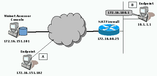
A VoIP connector creates a call group between Endpoint A and Endpoint B. The firewall is configured to allow bi-directional TCP and UDP flows on Port 10115, and bi-directional UDP flows on a selected port for the test call traffic. It is also configured to allow outgoing TCP flows on Port 10116.
|
Endpoint A |
Endpoint B |
|---|---|
|
Network address: 172.16.151.102 |
Network address: 10.1.1.1 |
|
NAT address: 172.16.100.1 |
Scenario 2: Both Endpoints behind NAT Device
In this scenario, the Vivinet Assessor Console is installed on a computer on the public Internet. Both endpoints A and B are behind a firewall performing network address translation. The firewall has 172.16.100.1 as the public address for Endpoint A, and 172.16.100.2 as the public address for Endpoint B.
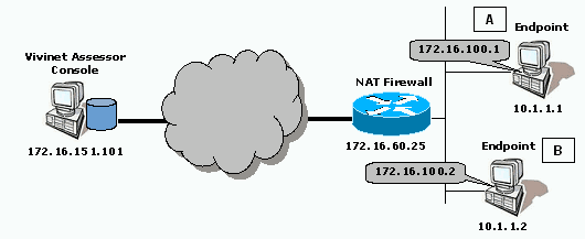
A VoIP connector creates a call group between Endpoint A and Endpoint B. The firewall is configured to allow bi-directional TCP flows on Port 10115, and outgoing TCP flows on Port 10116. With the following configuration, call traffic does not travel through the NAT device:.
|
Endpoint A |
Endpoint B |
|---|---|
|
Network address: 10.1.1.1 |
Network address: 10.1.1.2 |
|
Setup address: 172.16.100.1 |
Setup address: 172.16.100.2 |
Scenario 3: Endpoints behind Separate NAT Devices
In this scenario, the Vivinet Assessor Console is installed on a computer on the public Internet. Endpoint A is behind a firewall performing network address translation. Endpoint B is behind a second NAT firewall. The firewalls have 172.16.100.1 as the public address for Endpoint A and 172.16.100.2 as the public address for Endpoint B.
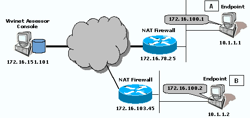
A VoIP connector creates a call group between Endpoint A and Endpoint B. Both firewalls are configured to allow bi-directional TCP and UDP flows on Port 10115, bi-directional UDP flows on a selected port for the test call traffic between the , and outgoing TCP flows on Port 10116.
|
Endpoint A |
Endpoint B |
|---|---|
|
Network address: 10.1.1.1 |
Network address: 10.1.1.2 |
|
NAT Address: 172.16.100.1 |
NAT address: 172.16.100.2 |
Scenario 4: Console and One Endpoint behind NAT Device
In this scenario, the Console and Endpoint A are behind a firewall performing network address translation. Endpoint B is located on the public Internet. The firewall has a public IP address of 172.16.100.1 for Endpoint A.
In most cases with this configuration, depending on the type of firewall used, the Console and endpoint would have to be installed on the same computer because most firewalls would not be able to forward traffic on a certain port to multiple endpoints

A VoIP connector creates a call group between Endpoint A and Endpoint B. The firewall is configured to allow bi-directional TCP and UDP flows on Port 10115, bi-directional UDP flows on a selected port for the test call traffic, and incoming TCP flows on Port 10116.
|
Endpoint A |
Endpoint B |
|---|---|
|
Network address: 10.1.1.1 |
Network address: 172.16.151.102 |
|
NAT address: 172.16.100.1 |
|
|
Setup address: 10.1.1.1 |
|
Scenario 5: Console behind NAT Device, Endpoints with Public Addresses
In this scenario, the Vivinet Assessor Console has a private address, behind a firewall performing network address translation. Both endpoints in a call group have public IP addresses on the Internet. The firewall has 172.16.100.3 as the public IP address for the Console computer.
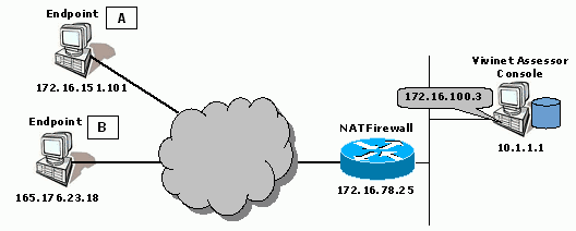
A VoIP connector creates a call group between Endpoint A and Endpoint B. The firewall is configured to allow outgoing TCP flows on Port 10115 for Console-to-endpoint setup communications, and incoming TCP flows on Port 10116 so that the endpoints can send results back to the Console.
|
Endpoint A |
Endpoint B |
|---|---|
|
Network address: 172.16.151.101 |
Network address: 165.176.23.18 |
Scenario 6: Console with Public Address; Endpoints on Either Side of NAT Device
In this scenario, the Vivinet Assessor Console is located on the public Internet. Two of the three endpoint computers are located behind a NAT device. One of these , labeled B in the diagram below, is used in more than one call group. It is paired with an endpoint on the private side for Call Group 1, and paired with an endpoint on the public side for Call Group 2. The firewall has 172.16.100.1 as the public IP address for Endpoint A, and 172.16.100.5 as the public IP address for Endpoint B.
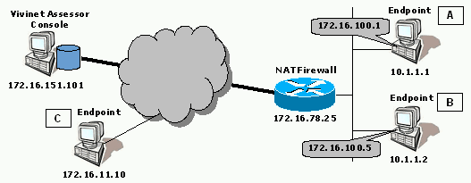
The endpoint with IP address 10.1.1.2 is created twice, using two different names.
Endpoint B is in the database with Network Address 10.1.1.2 and Setup Address 172.16.100.5 (Endpoint Name is B), and also with the same Network Address, no Setup Address, and NAT Address 172.16.100.5 (Endpoint Name is B-NAT).
NOTE:Vivinet Assessor allows you to create two endpoints with the same IP Network Address only if they have different names and different configurations for their Setup address or NAT address.
VoIP connectors create Call Group 1 between Endpoint A and Endpoint B and Call Group 2 between Endpoint B-NAT and Endpoint C. Call Group 2 tests the NAT device.
When sending test traffic through the firewall to Endpoint B-NAT, Endpoint C uses the NAT Address. However, with Call Group 1, the public addresses shown in the diagram above are only used for assessment setup between the Console and endpoints The call traffic between Endpoint A and Endpoint B will use the Network Addresses, bypassing the NAT firewall. This is important because actual VoIP calls between these network nodes will not cross the firewall.
The firewall is configured to allow bi-directional TCP and UDP setup flows on Port 10115, and bi-directional UDP flows on a selected port for the test call traffic between the endpoints in Call Group 2. It is also configured to allow outgoing TCP flows on Port 10116 so that the protected endpoints can send results back to the Console.
Here is a summary of the configuration for this scenario:
|
Endpoint Name |
Network Address |
Setup Address |
NAT Address |
|---|---|---|---|
|
Endpoint A |
10.1.1.1 |
172.16.100.1 |
|
|
Endpoint B |
10.1.1.2 |
172.16.100.5 |
|
|
Endpoint B-NAT |
10.1.1.2 |
|
172.16.100.5 |
|
Endpoint C |
172.16.11.10 |
|
|
The Setup Addresses configured for endpoints A and B are required; they allow the Console to contact those endpoints with assessment setup information through the NAT device.