9.1 Scenario: Building a View of Services and Supporting Technology
In this example, the goal is to build a view that shows services and the technology that supports them. This view displays current condition and state information from the technology components, to enable analysis of how the corresponding services are affected.
Information from an internal, IT‑maintained database has already been mined using a Data Integrator adapter. The result is a hierarchy that shows all business services with the servers that support them.
Use SCM to merge this hierarchy with information from three disparate network management systems that manage the servers that these services rely on. Correlation with technology state provides insight to the database information.
Most of the scenarios in this guide begin with a description of a hypothetical system containing a specific element hierarchy originating from a specific set of adapters. The steps used to perform various SCM functions use these hypothetical names. It is assumed that you will apply the examples to your own system, substituting the example element names with actual elements from your hierarchy.
The scenario described in this section uses the following:
-
A custom Data Integrator adapter that pulls in database information about IT services and the technology that supports them
-
Two Tivoli T/EC Adapters that provide state information about related technology
-
An HP OpenView Network Node Manager Adapter that provides state information about related technology
This example updates the view with new database information on a timely basis. In this situation, it is unnecessary to constantly update the configuration. Instead, the schedule runs daily to coincide with a shift change.
To merge elements from these three hierarchies into a single, new hierarchy:
-
In the Explorer pane under , use the option to create an element that is the parent of the new hierarchy.
In this example, name it Service Database.
-
Right-click the new element, then select > to open the Service Configuration Editor.
-
Define the element structures by identifying an existing hierarchy that drives the shape of the new tree.
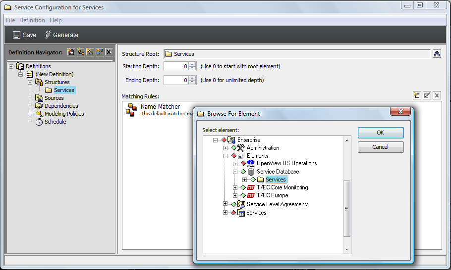
In this example, create a Structure definition that adds the element as the , as shown in the illustration below.
The hierarchy is a branch from a Data Integrator adapter that taps into an internal IT‑maintained database. It organizes technology (server information) by the service that it supports.
-
To display all elements contained in the hierarchy, leave and at 0.
-
Use the default Matching Rule to apply a simple name match to select elements.
-
Define the sources for the configuration by identifying an existing hierarchy that provides state and information to the new elements in the configuration.
This example creates three Source definitions that link to two different Tivoli T/EC adapters and an HP OpenView adapter that can provide state information about technology elements.
The first two Source definitions link to the folders of the Tivoli T/EC adapters as the . Use the default join rule to link state information to structure elements using a simple name match.

The third Source definition links directly to the root of an HP OpenView adapter by selecting as the . Use the default join rule on both definitions to link state information to structure elements using a simple name match.
-
To define and policy rules to specify how the configuration is generated and elements are correlated, expand , then click or .
This example does not add any settings. The configuration is generated using the definition to define the hierarchy structure and the definitions setting to integrate source information.
The defaults are retained to correlate configuration objects using a basic . Those objects that are matched are included in the new configuration tree.

-
Click to save configuration settings, then click to generate the new tree.
-
After the configuration is run and results are verified, create a schedule for the generation of the service configuration on a routine basis.