19.3 The System Panel Options
The System panel lets you perform actions that affect the appliance system in a general way. Use the tabs in this panel for changing and setting system time, changing the system password, restarting the appliance, upgrading the system, etc.
This section explains the following System Panel pages:
19.3.1 Timezone Page
Path: System > Timezone
Figure 19-4 Timezone Page
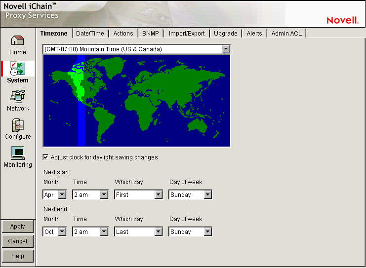
The Timezone page lets you specify a time zone for the appliance. It also lets you specify exactly when daylight saving time begins and ends.
The Time Zone Map: Lets you select a time zone for the appliance by clicking the map. The granularity offered through this method is adequate for most appliance installations. Additional flexibility in setting time is available on this page and from the command line. For more information on command line options, refer to the command line help for the set command and the time zone argument. See Section 19.7, Using Appliance Commands for more information.
Adjust Clock for Daylight Saving Changes: If you select this option, the appliance clock begins daylight saving time and resumes standard time on the dates and times defined in the fields below Next Start and Next End. For example, most U.S. time zones begin daylight saving on the first Sunday of April at 2:00 a.m. and resume standard time on the last Sunday of October at 2:00 a.m.
To set nonstandard daylight saving parameters in this page, select the start and end field values for Month, Time, Which Day, and Day of Week in their respective drop-down lists.
To set nonstandard parameters from the command line, refer to command line help for the set command and the dsstart, dsend, and dstime arguments. See the instructions for using command line online help in Section 19.7, Using Appliance Commands for more information.
19.3.2 Date/Time Page
Path: System > Date/Time
Figure 19-5 Date/Time Page
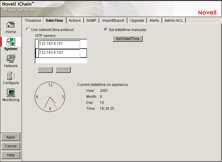
The Date/Time page lets you set the appliance system time so that the time stamps in cache logs are accurate and valid. An ISP, for example, might bill customers based on their access to the appliance. Accurate log time stamps are essential to issuing credible billing statements.
NOTE:iChain Proxy Services stamps log entries with Greenwich Mean Time (GMT). If the appliance is using an NTP server, the GMT stamp comes from that server. If the appliance is using a manually set time, iChain Proxy Services assumes the time is accurate and calculates the GMT value based on the appliance's time zone and daylight saving settings.
Use Network Time Protocol: Selecting this option turns the network time protocol on or off. This enables the appliance to synchronize its system time with an NTP server. Using an NTP server makes appliance cache log time stamps as reliable as possible. This can be especially important if you use the logs for customer billing. The appliance comes with two sample NTP servers: 132.163.4.101 and 132.163.4.103. You can remove these or add additional NTP servers.
IMPORTANT:When you specify an NTP server, synchronization between the NTP server clock and the appliance clock might not be immediate.
If the NTP server clock has an earlier time than the appliance clock, iChain Proxy Services slows the appliance clock down until the two are synchronized. This provides for proper incrementation of log files and other time-sensitive information during the synchronization process.
If the NTP server clock is later than the appliance clock, synchronization between the two is usually immediate. However, in certain situations you might observe the appliance clock incrementing by six hundred minute intervals. This is normal system behavior.
The fact that the Apply button changes from Wait back to Apply indicates only that the NTP configuration change has been made, not that the appliance clock is fully synchronized with the NTP server.
If the above features are problematic in your situation, you can set appliance time manually to the target time and then re-enable the NTP feature.
Set Time Manually: The following dialog box appears when you select this option and click Set Time. Set the date and time using the drop-down lists. Clicking OK immediately resets the system clock.
Figure 19-6 Set Time Dialog Box
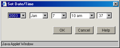
Use this option if NTP is not available to your appliance or you need to set a specific time for some reason.
19.3.3 Actions Page
Path: System > Actions
Figure 19-7 Actions Page
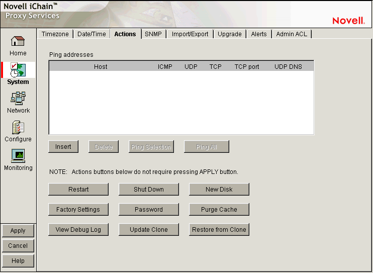
The Actions page lets you perform tasks related to the appliance hardware and software.
NOTE:Most changes made in the browser-based management tool are not effective until you click Apply. However, changes made in the Actions page are immediately effective.
Ping Addresses: You can check network connections using appliance ping functions by adding target hosts and port numbers to this list and then clicking Insert. Follow the address with a colon and a port number (an integer value from 0 to 65535) you want to ping. Using a port number lets you check whether a host has HTTP support (port 80), HTTP forward proxy support (port 8080), DNS support (port 53), ICP peer/parent support (port 3130), etc.
Restart: Shuts down the caching system and then restarts it. Configuration settings are retained but cached objects are removed.
Shut Down: Shuts down the caching system. The hardware remains turned on until it is manually powered off.
When the appliance has successfully shut down, a series of three beeps is repeated until the box is powered off.
New Disk: Scans for new disks that the system has not auto-detected.
Factory Settings: Resets the appliance to its original factory configuration as explained in Restoring Factory Settings. Passwords are retained. If you want to preserve other settings for later use on this or another appliance, see Import/Export Page.
Password: See Password Dialog Box.
Purge Cache: See Purge Cache Dialog Box.
View Debug Log: When an appliance experiences an abnormal shutdown because of a configuration error or other problem, iChain Proxy Services logs critical history information associated with the shutdown. Clicking this button displays the log in a separate browser window. You can then save the log file locally, print it, or e-mail it to Technical Support.
Update Clones: Each appliance stores a clone image that is initially the same as the factory image. If the appliance experiences an abnormal shutdown four times within a half hour period, or if it is restarted six times within a half hour period, iChain Proxy Services assumes the current configuration is faulty and automatically replaces it with the clone image.
You can overwrite the default clone image with an alternate configuration by selecting this option.
IMPORTANT:This process reboots the appliance, causing a temporary interruption of services.
Restore from Clones: Selecting this option restores the appliance to the configuration of the clone image (either the original factory clone image or an alternate clone image you have saved using the Update Clones option).
IMPORTANT:This process reboots the appliance, causing a temporary interruption of services. If the image being restored is the original factory clone image, you also need to reconfigure proxy services on the appliance or use a .nas file to restore these. See Restoring the Appliance to the Clone Image.
Password Dialog Box
Path: System > Actions > Password
Figure 19-8 Password Dialog Box
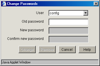
IMPORTANT:It is critical that you assign system passwords when initially configuring the appliance. Otherwise, access through Telnet, FTP, and the browser-based management tool is not restricted.
You can specify passwords for two users with different access privileges.
Users logging in using the View user password can view everything in the browser-based management tool and execute get commands from the command line. The Apply function and the set command are not available. The server license information is also not available.
Users logging in using the Config user password have full access to the browser-based tool and the command line interface.
Change: Immediately changes the password for the user selected.
Remove: Removes (sets to null) the password for the user selected.
Appliance passwords are case-sensitive.
Purge Cache Dialog Box
Path: System > Actions > Purge Cache
Figure 19-9 Purge Cache Dialog Box
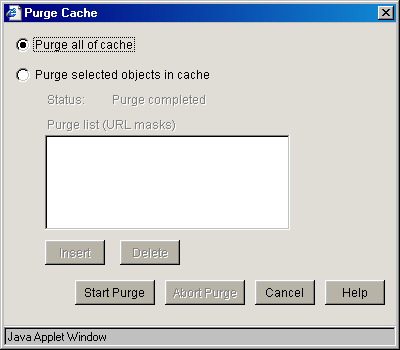
You can remove all cached objects from the appliance's cache, or you can perform a limited purging of cached objects based on URL masks. Purging cannot be undone.
Purge All of Cache: Starting the purge with this option selected will purge everything from the appliance's cache.
Purge Selected Objects in Cache: Selecting this option allows you to specify URL patterns or masks for the pages or sites whose objects you want to purge. When defining the masks, keep in mind that the appliance interprets everything in the URL mask between the asterisk wildcard (*) and the following delimiter as a wildcard. Delimiters include the forward slash (/), the period (.), and the colon (:) characters.
This option also allows purging of cache objects whose URL contains a specified query string or cookie. This mask is defined by placing a question mark (?) at the start of the mask followed by text strings and wildcards as necessary. String comparisons are not case sensitive. For example, ?*=SPORTS will purge all objects with the text “=SPORTS” or any other combination of uppercase and lowercase letters for “=SPORTS” following the question mark in the URL.
19.3.4 SNMP Page
Path: System > SNMP
Figure 19-10 SNMP Page
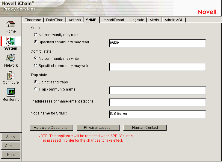
The SNMP page lets you configure the appliance with basic SNMP information so the appliance can communicate with your SNMP management workstations.
The appliance's SNMP implementation follows the ISO SNMP version 1 standard outlined in RFC 1067: A Simple Network Management Protocol.
When SNMP-enabled appliance components start, they register with the system. When the system receives a request for a specific SNMP parameter, it knows which component to contact to obtain the information.
Each appliance contains an ichain.mib file in the sys:\etc\proxy\data directory. To see a list of standard SNMP parameters, retrieve this file using the FTP get command and compile it for use with your SNMP management software.
If you specify a trap community name and specify an SNMP management workstation in the SNMP page, all alerts you check in the Alerts Page (see Alerts Page) are automatically sent as SNMP traps even if you have not configured syslog or e-mail alert notification on the Alerts page.
Monitor State: Allows you to specify community Read access and the community name or password to be used. Community names must contain only ASCII characters and must not have spaces.
Control State: Allows you to specify community Write access and the community name or password to be used. Community names must contain only ASCII characters and must not have spaces.
IMPORTANT:The default name or password for the control community is No, meaning that control access is turned off. You can reset this value. However, this is not normally recommended, because the control community password is stored as clear text and could allow unauthorized write access to SNMP parameters on the appliance.
Trap State: Allows you to either specify that traps are not sent, or to specify a community (location, IP octets, or other identifier) from which traps are sent to the management stations you designate. Community names must contain only ASCII characters and must not have spaces.
IP Addresses of Management Stations: One or more management station IP addresses, separated by semicolons.
Node Name for SNMP: Lets you specify a node name for management of the appliance through SNMP.
The buttons below the node name field let you enter additional information regarding the hardware, the appliance's physical location, and information regarding the person responsible for the appliance.
19.3.5 Import/Export Page
Path: System > Import/Export
Figure 19-11 Import/Export Page
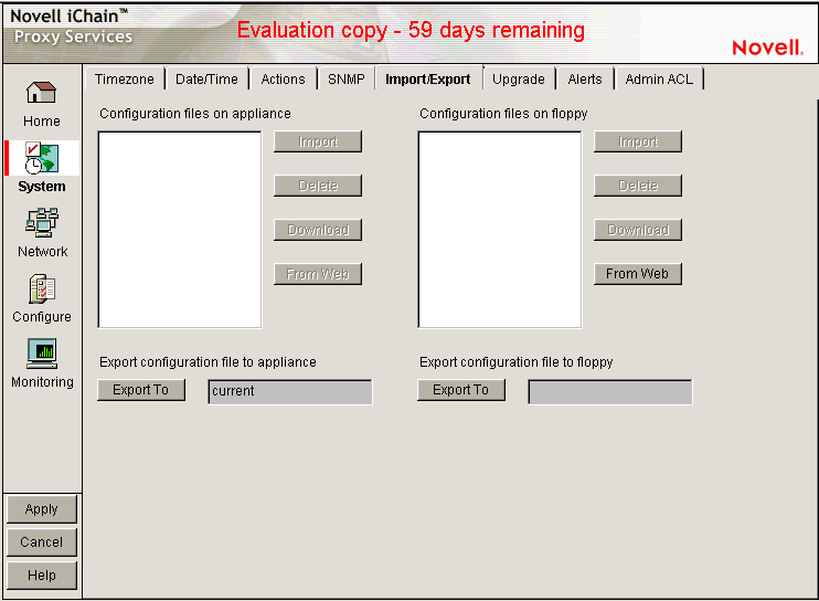
The Import/Export page lets you manage appliance configuration files on the appliance and on floppy disk.
Configuration Files on Appliance: Displays a list of all of the configuration files stored on the appliance. These files are used to instantly configure the appliance, rather than using the GUI, command line, or Telnet to make individual changes. The appliance automatically updates the configuration file, CURRENT, each time you apply a change to iChain Proxy Services. The .nas extension of these files is not shown in this list but is supplied by the server.
You can download, import, and delete any file in this list. You can also copy a configuration file from any URL to the appliance. The Download option opens the file in a separate browser window. The Import option changes the appliance configuration from its current settings to those contained in the selected configuration file. The Delete option removes the selected configuration file from the appliance. The From Web option lets you specify the URL for the configuration file being copied to the appliance. If the file is in a secure area or is being downloaded using SSL (HTTPS:), you can also enter a username and password for authentication.
Configuration Files on Floppy: Displays a list of all the configuration files stored on the floppy disk located in the appliance's floppy drive. You can download, import, and delete any file in this list. You can also copy a configuration file from any URL to a floppy in the appliance's floppy drive. The previous section contains more detail regarding the Import, Delete, Download, and From Web options.
IMPORTANT:It is easy to confuse the diskette in the appliance's floppy drive with one located in your configuration workstation. Only the former is accessible through the browser-based management tool.
Export Configuration File to Appliance / Export Configuration File to Floppy: Clicking the button under one of these titles creates a configuration file on the appliance or on the diskette in the appliance's floppy drive.
Files saved using the Export feature contain the complete configuration of the appliance at the time of export. The default filename is current.nas. You can specify any DOS-style eight-character name. Names are not case sensitive. Each file has a .nas extension that is not displayed in the list or specified when the file is created, but is automatically appended by the system.
WARNING:Do not create .nas filenames longer than eight characters, because the system might overwrite a previous file. For example, If you create 000000005.nas and 000000006.nas, the system overwrites the older file.
19.3.6 Upgrade Page
Path: System > Upgrade
Figure 19-12 Upgrade Page
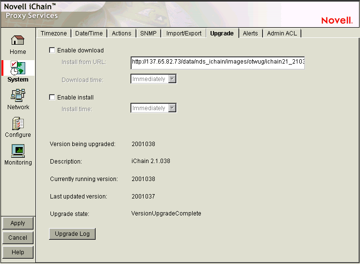
The Upgrade page lets you set patch and upgrade parameters so you can download and install patches to the appliance. It also lets you uninstall the most recently applied patch.
Over-the-wire upgrades are secured through signing.
NOTE:We recommend that you update the appliance's clone image after an upgrade. See Restoring the Appliance to the Clone Image, Actions Page, and Section 19.8, Performing Patch Upgrades for more information.
Enable Download: Lets you set the appliance to automatically download updates. If you select this option and enter the URL for the patch in the Install from URL field, it is downloaded as scheduled in the Download Time field. A valid entry for Install from URL is any valid URL or DNS name for a Web site.
Enable Install: Lets you set the appliance to automatically install patches. If you select this option, patches downloaded to the appliance are automatically installed as scheduled in the Install Time field.
Version Being Upgraded: Each update has a version number. The version of the current update appears in this field the moment the update process begins. You cannot upgrade the proxy server to a lower version than the one currently installed.
Description: A text name associated with the update file.
Currently Running Version: The update version number the appliance is currently running. Before installing the first update, this number is 0.
Last Updated Version: The update version number of the last update applied. For example, if you are currently running update version 3, this number might be 2.
Upgrade State: A state value indicating upgrade status. State values include Not Started, Download Pending, Version Download Complete, etc. The field is updated each time you click Upgrade.
Upgrade Log: Displays the text messages that have been generated by the upgrade process.
19.3.7 Alerts Page
Path: System > Alerts
Figure 19-13 Alerts Page
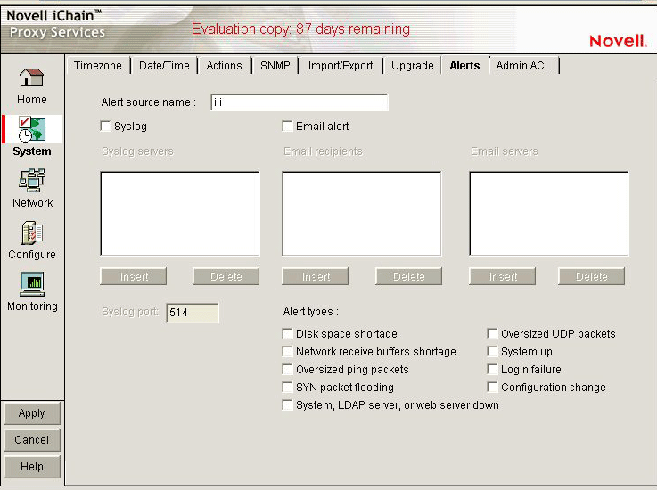
The Alerts page lets you configure the appliance to send notification of generated system alerts to a network server hosting a Syslog service and to a list of e-mail recipients.
Alert Source Name: This identifies the appliance as the source of an alert. The system inserts this in the From field of an e-mail alert and in the Syslog alert message. Be sure to use only those characters that are compatible with the e-mail servers you are specifying. Using spaces and other characters might prevent an e-mail server from accepting the alert message.
Syslog: Selecting this option enables syslog alerts. Alert messages are then sent to one of the syslog servers.
E-mail Alert: Selecting this option enables e-mail alerts. Alert messages are then sent to all of the e-mail recipients. However, in order for this type of alert to function properly, you must not have any spaces in the alert address.
IMPORTANT:For this feature to work, e-mail servers must be able to relay e-mail from the appliance without authentication.
Because of increasing security risks, many e-mail servers have this feature disabled.
If you plan to have the appliance use e-mail alerts you must either ensure that the e-mail server can relay unauthenticated messages, or you must configure the server to accept mail from the appliance without authentication.
Syslog Servers: This is a list of syslog servers to which the appliance sends alerts. The appliance pings servers in the list, starting with the first server, until it receives an acknowledgement. It then sends a syslog alert using UDP to the responding server.
E-Mail Recipients: This is a list of e-mail recipients to whom the appliance sends alert e-mails. The appliance sends e-mails to all addresses in the list.
E-Mail Servers: This is a list of e-mail servers through which the appliance routes alert e-mails. E-mails are sent to the first e-mail server in the list. If the server doesn't respond, other servers are accessed in turn until the transmission is successful.
Syslog Port: This is the port the syslog server listens for syslog alerts on. The default port is 514, but this can be changed if required.
Alert Types: Appliance-generated alerts are sent for the following conditions. You enable or disable notification of generated alerts to the configured syslog server, and you e-mail recipients by selecting or deselecting an alert type.
-
Disk Space Shortage: The appliance generates this alert when disk space is low on the OS (sys:) or Log (log:) volumes.
-
Network Receive Buffers Shortage: The appliance generates this alert when the network receive buffers are low.
-
Oversized Ping Packets: The appliance generates this alert when TCP/IP receives an oversized (greater than 10 KB) PING packet.
-
SYN Packet Flooding: The appliance generates this alert when TCP/IP detects a SYN packet flooding attack (half-open connections).
-
System, LDAP server, or web server down: The appliance generates this alert each time the appliance is shut down properly or restarted manually.
-
Oversized UDP Packets: The appliance generates this alert when TCP/IP receives an oversized (greater than 16 KB) UDP packet.
-
System Up: The appliance generates this alert each time the appliance starts.
-
Login Failure: The appliance generates this alert for all failed login attempts, including failed login attempts to proxy accelerators. The alert contains the IP address of the client making the unsuccessful attempt. Unsuccessful Telnet login failures are not detected.
-
Configuration Change: The appliance sends this alert each time the appliance's configuration is changed and each time the appliance is initialized or re-initialized.
19.3.8 Admin ACL Page
Path: System > Admin ACL
Figure 19-14 Admin ACL Page
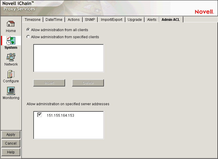
The Admin ACL page lets you regulate access to appliance administrative functions in the browser-based management tool and the command line interface. You can restrict administrative client access and limit the appliance IP addresses through which administrative access is allowed.
Allow Administration from All Clients: This option is selected by default and allows access to appliance administrative functions from any IP address.
Allow Administration from Specified Clients: When you select this option you must also insert at least one IP address from which IP administrative access is allowed. Otherwise, the system deselects the option to prevent a global lockout.
NOTE:If you do not include the IP address from which you are specifying client access, and you click Apply, the address is not available for future administration sessions unless it is added later.
Allow Administration on Specified Server Addresses: This list contains all appliance IP addresses and indicates which are enabled for administrative access. The first addresses assigned to each network adapter are enabled for administration access by default. You change administrative access by selecting and deselecting addresses in the list. The system doesn't allow deselecting all addresses. If this is attempted, the system reverts to the default setting by re-selecting all first-assigned addresses.